


Chapter 3 49
Troubleshooting
Flow Diagrams for Troubleshooting
Flow Diagrams for Troubleshooting
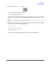
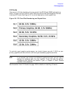
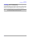
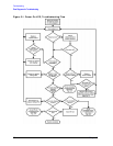
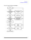
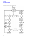
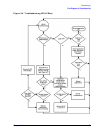
The following four figures contain troubleshooting flowcharts you can follow to isolate a
failing Field Replaceable Unit (FRU). Figure 3-1., “Power On LCD, Troubleshooting Flow,”
contains the main troubleshooting flowchart. Figures 3-2 through 3-4 then contain
flowcharts for console, bootable device, and HP-UX troubleshooting, respectively.
NOTE
For the system to power up, the left side panel must be properly seated in the
mainframe chassis to engage the safety interlock switch.