


Chapter 4 147
Field Replaceable Units
FRU Removal and Replacement
The System Board
The system board contains the I/O section, computer main memory, CPU, and all of the
circuitry and connections that control how the workstation’s hardware and operating
system interact with each other. If any of the components on the system board are
defective, you must remove the system board from the workstation chassis.
The system board in the B1000/C3000 workstation is mounted on a tray. The following
procedures describe how to remove and replace the system board tray assembly as a
complete unit.
Removing the System Board
To remove the system board tray assembly, do the following:
1. Remove the left side panel as explained in the section “Opening the Left Side Panel of
the System Unit” in this chapter.
NOTE
Remove the terminators on the rear panel of the workstation.
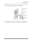
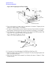
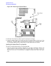
2. Remove the two T-15 Torx screws that secure the system board tray assembly to the
rear panel of the workstation.
3. Remove the system unit power supply as covered in the section “System Unit Power
Supply” in this chapter.
4. Remove the hard disk drive fan as described in the section “Removing the Fan from the
Hard Disk Drive Area”.
5. Remove the DIMM cards as explained in the section “Removing Memory” in this
chapter.
6. Remove the PCI retainer, the I/O cards from their PCI slots and the air divider as
covered earlier in this chapter.
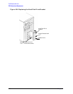
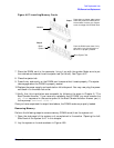
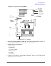
7. Unplug the following cables from the system board:
a. Floppy disk drive data cable
b. CD drive data cable
c. Hard disk drive fan cable
d. Fan/Speaker cables
e. LCD ribbon cable
f. CD drive audio cable
g. System board fan cables (2)
h. Ultra2 Wide LVD SCSI cable