


Chapter 4 129
Field Replaceable Units
FRU Removal and Replacement
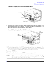
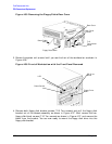
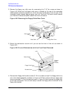
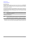
Figure 4-40. Plugging in the Data and Power Cables
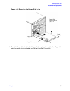
9. Verify that the data and power cables are positioned to come out of the top edge of the
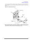
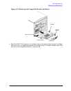
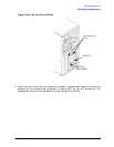
rear floppy cover. This edge is rounded to prevent cutting of the cables. See Figure 4-41.
Next tighten the T-15 rear cover screw.
Figure 4-41. Replacing the Rear Floppy Cover
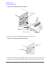
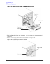
10.Complete the installation of the floppy disk drive by replacing the front and side panels
of the system unit. You should also make sure that all cables are positioned within the
system unit so that they do not hang loosely. This will prevent damage to the cables.
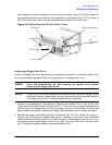
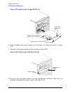
Removing a Floppy Disk Drive
1. Perform the procedures in the sections “Opening the System Unit Front Panel” and
“Opening the Left Side Panel of the System Unit.” The front panel needs to be opened so
you can remove the floppy disk drive from the system unit chassis. The left side panel
needs to be opened so you can get to the floppy’s data connector and its power connector.
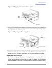
Data Cable
Power
Cable
T-15
Torx/slotted
Screw
Floppy Rear Cover
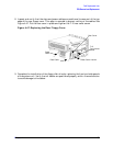
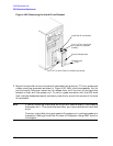
Power Cable
Data Cable