


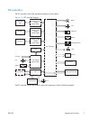
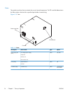
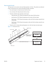

Fuser-control circuit
The fuser-control circuit monitors and controls the temperature in the fuser. The product uses on-demand
fusing. The fuser-control circuit consists of the following major components:
●
Fuser main heater (H1): Heats the center of the fuser sleeve
●
Fuser sub heater (H2): Heats the ends of the fuser sleeve
●
Thermistors; detect the fuser temperature (contact type)
◦
Sleeve thermistor (TH1): Detects the temperature at the center of the fuser sleeve
◦
Main thermistor (TH2): Detects the temperature at the center of the fuser heater
◦
Sub thermistor 1 (TH3): Detects the temperature at the end of the fuser heater nearest the front
of the product
◦
Sub thermistor 2 (TH4): Detects the temperature at the end of the fuser heater nearest the rear
of the product
●
Thermal fuse (FU1): Prevents abnormal temperature rise in the fuser heater (non-contact type)
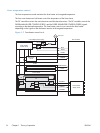
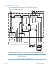
Figure 1-6 Fuser-control circuit
H1
FUSER TEMPERATURE signal
Pressure roller
FUSER HEATER
CONTROL signal
TH4
TH2
FU1
TH3
Fuser sleeve
Fuser heater
control circuit
Fuser heater
safety circuit
Low-voltage power supply
DC controller
H2
TH1
Front of engine
ENWW
Engine-control system
15