


Appendix C
Site Preparation
Grounding Systems
108
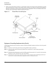
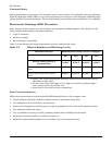
• Good—Use the raised floor structure as a ground grid. In this case, the floor must be designed as a ground
grid with bolted down stringers and corrosion resistive plating (to provide low resistance and attachment
points for connection to service entrance ground and server equipment). The use of conductive floor tiles
with this style of grid further enhances ground performance.
Figure C-1 Raised Floor Ground System
Equipment Grounding Implementation Details
If it has been determined to be necessary, connect all Hewlett-Packard equipment cabinets to the site ground
grid as follows:
Step 1. Attach one end of each ground strap to the applicable cabinet ground lug.
Step 2. Attach the other end to the nearest pedestal base (raised floor) or cable trough ground point
(nonraised floor).
Step 3. Check that the braid contact on each end of the ground strap consists of a terminal and connection
hardware (a 1/4-in. (6.0-mm) bolt, nuts, and washers).
Step 4. Check that the braid contact connection points are free of paint or other insulating material and
treated with a contact enhancement compound (similar to Burndy Penetrox).