


Chapter 2
Installation
Unpacking the Server
30
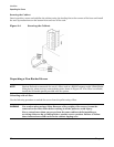
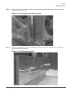
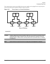
Step 2. Attach the other end of the CMA to the server using the thumb screws that came with the CMA.
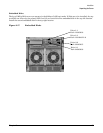
Figure 2-16 Attaching CMA to the Server
Installing Add-On Products
This section explains load orders and dependencies for add-on products. For physical installation procedures,
refer to that components replacement procedure in Chapter 4, “Removal and Replacement.”
If installing add-on products to an existing server, follow operating system backup and shutdown procedures
before powering off the server.
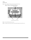
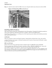
Cell Boards
The server requires at least one cell board to operate. Install the first cell board slot 1 (lower slot) and the
second cell board in slot 0 (upper). Cell Board 0 enables the PCI cards in Chassis 0 and Cell Board 1 enables
the PCI cards in Chassis 1.
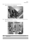
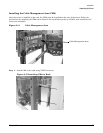
MP Core I/O Cards
MP Core I/O consists of two cards that must be installed in pairs: the MP/SCSI and the LAN/SCSI.
The first (primary) set of MP Core I/O cards is installed as follows: MP/SCSI in MP/SCSI slot 1 (lower slot)
and LAN/SCSI in PCI slot 8 of Chassis 1 (from the rear, the extreme right-hand PCI slot).
The second set of MP Core I/O cards is installed as follows: MP/SCSI in MP/SCSI slot 0 and LAN/SCSI in PCI
slot 1 of Chassis 0. Cell Board 0 is required to enable the MP/SCSI slot 0 (upper slot) and LAN/SCSI slot 1 in
Chassis 0 (from the rear, the extreme left-hand PCI slot).