


Chapter 1
Introduction
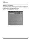
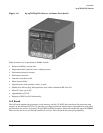
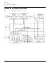
Detailed hp rp7405/rp7410 Description
9
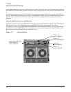
PDH Riser Board
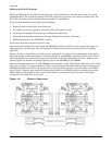
The PDH riser board is a daughter card for the cell board. It contains a micro-processor memory interface
microcircuit, processor-dependent hardware (PDH) including the processor dependant code (PDC) Flash
memory, and a manageability micro-controller, called SINC, with associated circuitry. The PDH obtains cell
board configuration information from cell board signals and from the cell's LPM. See the PDH Riser Board
ERS for operational details.
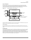
The memory interface microcircuit is the heart of the PDH. It provides the CC access to the PDH space by a
4-bit, 50-75 MHz bus. This microcircuit also supports an interrupt mechanism to the CC that can interrupt a
processor for the PDH. It provides access to the FLASH ROM and scratch RAM memory chips together with
the external registers and an interface to an I
2
C micro controller (SINC) that monitors sensors throughout
the system. It also controls system reset and initialization signals, as well as the low-level debugger (LDB)
port, UART, semaphore register, and GPIO pins. It is the primary master for a Serial Presence Detect bus.
The PDH supports up to 4 MB of address space for ROM (FLASH) to hold the PDC firmware.
The non-volatile memory and scratch RAM have been combined and placed in a 512KB battery-backed SRAM
DIMMs
Custom designed by Hewlett-Packard, each DIMM contains 36x4 SDRAM memory components similar to
PC-133 memory but qualified to run at 125MHz. They have an low-voltage TTL interface. The CEC does not
support traditional DRAMs.
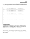
The hp rp7405/rp7410 supports DIMMs with 128, 256, 512, and 1024 Mbit devices. Table 1-3 shows each
DIMM supported with its associated capacity, the resulting total system capacity, and the memory component
density.
DIMMs must be loaded in sets of four at specific locations. For best performance, loading sets of eight DIMMs
is recommended.
Main Memory Performance Latency to main memory is an important parameter in determining overall
system performance. With memory busses running at 125 MHz, the latency for a page hit is 8.5 cycles (68ns),
the latency for a page closed is 11.5 cycles (92ns), and the latency for a page miss is 14.5 cycles (116ns).
Cells and nPartitions
NOTE In the following discussion, the term “cell” refers to a cell board.
A cell board that has an I/O link to a bootable device and a console (usually supplied by an MP Core I/O card)
is a potential boot cell. The cell that contains the boot console I/O path is the called the root cell. Both cells are
potential root cells. The primary or default root cell in a single nPartition system is the bottom cell (cell 1).
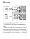
An nPartition (also called a Protection Domain) is a cell(s) running the same OS and sharing processes and
memory space among the components. Each nPartition must have one root cell and may have both. The hp
rp7405/rp7410 has only two possible nPartition configurations: single or dual. The additional cell that may be
part of the nPartition does not require I/O links nor MP Core I/O cards.
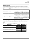
Table 1-3 hp rp7405/rp7410 DIMMs
DIMM Capacity Total Capacity Memory Component Density
512 Mbyte 16 Gbytes 128 Mbit
1G Byte 32 Gbytes 256 Mbit