Appendix C
Site Preparation
Environmental Elements
112
• Underfloor air distribution system—Downflow air conditioning equipment located on the raised floor of
the computer room uses the cavity beneath the raised floor as plenum for the supply air.
Perforated floor panels (available from the raised floor manufacturer) should be located around the
perimeter of the system cabinets. Supply air emitted though the perforated floor panels is then available
near the cooling air intake vents of the computer system cabinets.
• Ceiling plenum air distribution system—Supply air is ducted into the ceiling plenum from upflow air
conditioning equipment located in the computer room or from an air handling unit (remote).
The ceiling construction should resist air leakage. Place perforated ceiling panels (with down discharge
air flow characteristics) around the perimeter of the system cabinets. The supply air emitted downward
from the perforated ceiling panels is then available near the cooling air intake vents of the computer
system cabinets.
Return air should be ducted back to the air conditioning equipment though the return air duct above the
ceiling.
• Above ceiling ducted air distribution system—Supply air is ducted into a ceiling diffuser system from
upflow air conditioning equipment located in the computer room or from an air handling unit (remote).
Adjust the supply air diffuser system grilles to direct the cooling air downward around the perimeter of
the computer system cabinets. The supply air is then available near the cooling air intake vents of the
computer system cabinets.
Air Conditioning System Installation
All air conditioning equipment, materials, and installation must comply with any applicable construction
codes. Installation of the various components of the air conditioning system must also conform to the air
conditioning equipment manufacturer’s recommendations.
Humidity Level
Maintain proper humidity levels. High humidity causes galvanic actions to occur between some dissimilar
metals. This eventually causes a high resistance between connections, leading to equipment failures. High
humidity can also have an adverse affect on some magnetic tapes and paper media.
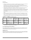
Table C-1 Computer Room Environment
Parameter Operating Limits
Recommended
Operating
Range
Maximum Rate of
Change (per hour)
Non-Operating
Ranges
Temperature
a
a. The temperature ranges stated are at 0 to 5,000 feet. The maximum operating temperature must
be de-rated by 1° C/1,000 feet from 5,000 to 10,000 feet.
41° - 95° F
(5° - 35° C)
68° - 77° F
(20° - 25° C)
20° C/hour -40° C - +70° C
Humidity 15% - 80%
with no condensation
(40% - 55% recommended)
40% - 55% RH
non-condensing
30% RH/hour
non-condensing
90% RH
non-condensing
@ 65° C (149° F)


