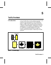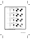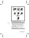
Figure 5-3 demonstrates the transparency modes. In the
first example (1a), the transparency mode for both the
source image and the pattern is transparent. Since the
source mode is “transparent,” only the non-white region
(the circle) of the source image is overlaid on the
destination. Since the pattern mode is also transparent, the
patterned source image is applied only to the white areas of
the destination.
In the second example (1b), the source mode is still
“transparent,” but the pattern mode is “opaque” – so the
pattern’s white pixels are applied to the destination. The
resulting image shows the entire circle region visible and
patterned.
In the third example (1c), the source mode is “opaque” and
the pattern mode is transparent. Since the source mode is
opaque, the entire source image (the circle and the
surrounding square) appears overlaid onto the destination.
The pattern, however, is allowed to pour through only onto
the white-pixeled area of the destination. The circle is
visible in the result, but only two opposing quarters appear
patterned.
In the fourth example (1d), both source and pattern modes
are “opaque.” The entire source image is overlaid onto the
destination, and the entire circle is patterned.
This example uses the default ROP. The output may appear differently depending on the colors used.
Figure 5-2.Figure 5-2. Opaque and Transparency ModesOpaque and Transparency Modes
5-4 The PCL Print Model5-4 The PCL Print Model


