


user-defined algorithm in this situation causes the default
algorithm to be used. The default is used until the
algorithm is changed to something other than user-defined,
or until you specify a device-dependent color space.
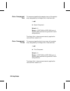
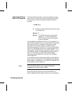
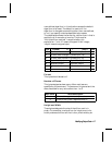
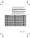
The table below shows the format for a dither matrix that is
applied to all three color primaries. The format for
“multiple dither matrices” is supplied after this
explanation. (“uint 16” means unsigned 16-bit integer;
“ubyte” means unsigned byte.)
Byte 15 (msb) 8 7 (lsb) 0 Byte
0 Format = 0 Number of planes = 1 1
2 Dither matrix height in pixels (uint 16) 3
4 Dither matrix width in pixels (uint 16) 5
6 byte #0 (ubyte) byte #1 (ubyte) 7
8 byte #2 (ubyte) byte #3 (ubyte) 9
•
•
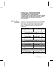
Format
This byte should be set to 0.
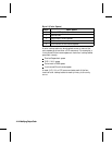
Number of Planes
This byte designates how many dither matrices are
specified by the command. The command is ignored and the
data discarded for any value other than 1 or 3.
Byte Value Value Description
1 One matrix applied to all primaries
3 Each primary has a separate matrix
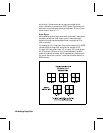
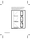
Height and Width
These bytes designate the size of the dither matrix in
pixels. For example, a value of four for height and six for
width produces a dither cell that is four pixels wide by six
Modifying Output Color 4-7Modifying Output Color 4-7