


are applied to the destination image (see the note below).
Setting the source transparency mode to 1 (opaque)
applies the source image’s white pixels to the destination
image; with a setting of 0 (transparent), these pixels
have no effect on the destination.
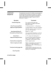
Pattern Transparency Mode—The transparency or
opaqueness of the “white pixels” in the pattern (see the
note below). When set to 0 (transparent), these pixels
have no effect on the destination; when set to 1 (opaque),
they are applied through the black pixels of the source
pattern to the destination.
Logical Operations—the Print Model uses logical
operations, such as AND, OR, XOR, and NOT when
determining which bits of the source, pattern, and
texture become part of the resulting image. The Logical
Operations command (?*l#O) can vary the logical
operation used, thus varying the outcome.
Note For RGB color images, “white” pixels are those for which all
color primaries are greater than or equal to their white
reference values. For CMY color images, “white” pixels are
those for which all color primaries are less than or equal to
their white reference values.
When using Render Algorithm 2 (?*t2J) for halftoning,
black pixels are affected by the transparency mode instead
of white pixels.
For all rendering algorithms, white dots introduced in the
dithering process are not subject to transparency modes.
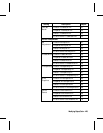
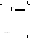
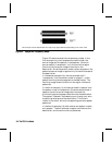
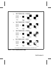
Figure 5-2 illustrates the effects of the source and pattern
transparency modes on the final image. (The transparency
modes work a little differently with rectangular area
fill—see “Pattern Transparency for Rectangular Area Fill”
near the end of this chapter.)
The PCL Print Model 5-3The PCL Print Model 5-3