


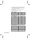
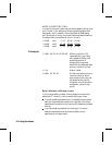

MODE 0: INDEXED BY PLANE
In mode 0 (default), successive planes of data are sent for
each raster row. A plane contains one bit for each pixel in a
row. A pixel is not fully defined until it has received all the
planes for that row. The planes in a row form index
numbers that define a pixel by selecting a palette entry.
Assuming 3 bits per index, the underlined column of bits
below is the palette index for pixel 3 of row 1 (i1 is lsb; i3 is
msb). Note that the Transfer Raster Data by Plane
command (?*b#V) is used for all planes except the last
plane of each row, which uses the Transfer Raster Data by
Row command (?*b#W).
?*b#V row 1 plane 1 i1 i1
i1 i1 i1
?*b#V plane 2 i2 i2
i2 i2 i2
?*b#W plane 3 i3 i3
i3 i3 i3
?*b#V row 2 plane 1 i1 i1 i1 i1 i1
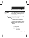
Example:
?*v6W 00 00 03 08 08 08 # Binary data for CID
represented in hex. Sets
color space to RGB, pixel
encoding mode to 0, palette
size to 8 (3 planes), last 3
bytes ignored.
?*r1A # Start raster.
?*b1V10110000 . . . # Transfer plane 1 (the first
bit for each pixel in the first
row). Combining each bit
with its corresponding bit in
the other planes forms the
palette index number for
that pixel.
?*b1V01110000 . . . # Transfer plane 2 (the
second bit for each pixel in
the row).
2-8 Using Color Modes2-8 Using Color Modes