


Pixel Placement HP PCL 5 printers place pixels at the intersection of the
squares of a theoretical, device-dependent grid covering the
printable area on the page. Depending on the image and
the logical operation in effect, a problem may occur when
the sides of two polygons touch each other—the pixels along
the common border may be printed twice or not at all. For
example, a source rectangle consisting of all 1’s that is
XORed with a destination consisting of all 1’s produces a
white rectangle; but if another source rectangle is placed
on the page touching the first rectangle, the two rectangles
will be white-filled except at their common border
( (1^1) ^1 = 1).
To correct situations where this problem occurs, the PCL
printer language provides a choice of pixel placement
models: grid intersection and grid centered. The grid
intersection model is the default: pixels are rendered on the
intersections of the device-dependent grid covering the
page. In the grid-centered model, the number of rows and
columns are each reduced by one, and pixels are placed in
the center of the squares, rather than at the intersections.
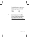
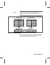
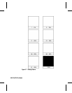
The following example illustrates the concepts of the two
models (see Figure 5-5). Assume a rectangle extends from
coordinate position (1,1) to position (3,4). As shown below,
for the same coordinates, the grid-centered model produces
a rectangle that is one dot row thinner and one dot row
shorter than the grid intersection model. Thus, the
grid-centered model should be selected when two or more
polygons on a page may share a common border.
Since PCL printers print only at the intersections of the
grid, the actual implementation of the grid-centered model
is shown on the right.
The PCL Print Model 5-21The PCL Print Model 5-21