


Removal and Replacement Procedures80
System Board
This section provides additional information about the system board.
• “System Board Components” on page 80
• “System Board Architecture” on page 81
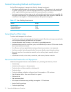
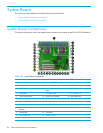
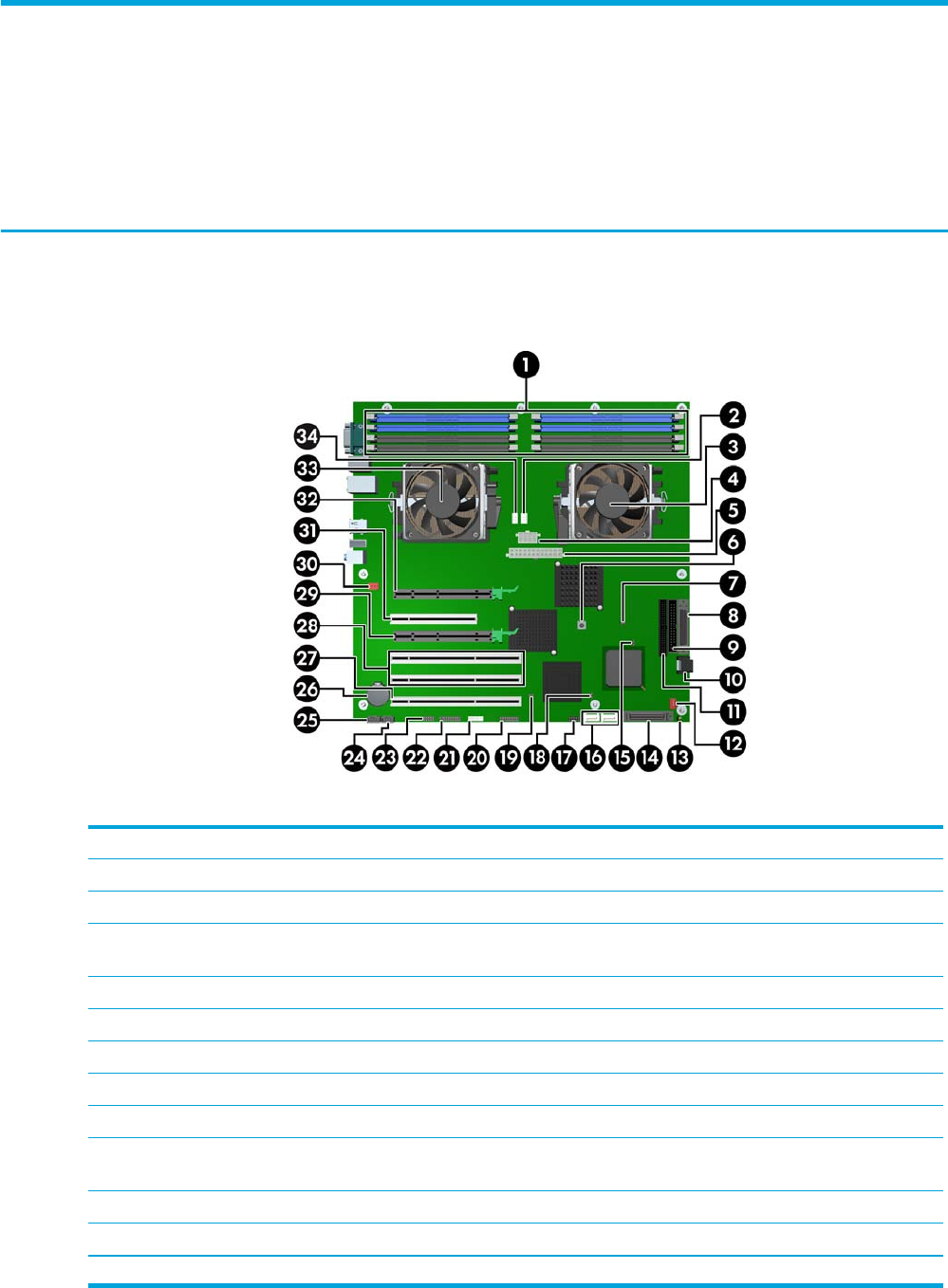
System Board Components
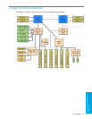
The following illustration shows the system board connectors and sockets on the HP xw9300 Workstation.
Table 4-18 System Board Components
1 Memory module pairs 13 Hard disk activity LED 25 CD audio
2 Processor 0 fan 14 Internal SCSI (Channel 1) 26 Battery
3 Processor 0 15 Password jumper 27 PCI-X 133
4 CPU0/1 power connector 16 Serial ATA ports 2 (left) and 3
(right)
28 PCI-X 100
5 Main power 17 Front panel USB 29 PCI Express x16
6 Clear CMOS button 18 PCI-X 133 slot speed 30 Rear chassis fan
7 Boot block jumper 19 PCI-X 100 slot speed 31 PCI
8 External SCSI (Channel 0) 20 Front control panel 32 PCI Express x16
9 Diskette drive 21 Front IEEE 1394 33 Processor 1
10 Serial ATA ports 0 (top) and 1
(bottom)
22 Trusted Platform Module 34 Processor 1 fan
11 Primary IDE* 23 Front panel
12 Front chassis fan 24 Auxiliary audio
*The Primary IDE connector is only used for optical drives.