


satisfactory, CICS schedules the new resource for OPNDST in order to complete
the logon request. If the installation process fails, then the control program is driven
again, as though a DELETE had occurred. (See the section “The autoinstall control
program at DELETE” on page 525 for details.) This is necessary to allow the
program to free any allocations (for example, terminal identifiers) made on the
assumption that this INSTALL request would succeed.
If the return code is not zero, then CICS rejects the connection request in the same
way as it rejects an attempt by an unknown terminal to log on to CICS when
autoinstall is not enabled.
For all autoinstall activity, messages are written to the transient data destination
CADL. If an INSTALL fails, a message is sent to CADL, with a reason code. You
can therefore check the output from CADL to find out why an autoinstall request
failed.
If an autoinstall attempt fails for lack of an exact match, then details of the “best
failure” match between a model and the BIND image are written to the CADL
transient data destination.
The message takes the following form:
DFHZC6987 BEST FAILURE FOR NETNAME: nnnnnnnn,
WAS MODEL_NAME: mmmmmmmm,
CINIT BIND: cccccccc...,
MODEL BIND: bbbbbbbb...,
MISMATCH BITS: xxxxxxxx...
where
v ‘nnnnnnnn’ is the netname of the LU which failed to log on.
v ‘mmmmmmmm’ is the name of model that gave the best failure. (That is, the one
that had the fewest bits different from the BIND image supplied by VTAM.)
v ‘cccccccc...’ is the CINIT BIND image.
v ‘bbbbbbbb...’ is the model BIND image.
v ‘xxxxxxxx...’ is a string of hexadecimal digits, where ‘xx’ represents one byte, and
each byte position represents the corresponding byte position in the BIND image.
A bit set to ‘1’ indicates a mismatch in that position between the BIND image
from VTAM and the BIND image associated with the model.
A suggested course of action is as follows:
1. Determine whether a model such as ‘mmmmmmmm’ is suitable. If there are
several models that have identical BIND images, differing only in end-user
options, then only the first such model is named in the above message. It will
be up to your control program to make the choice, when the logmode table
entry is corrected.
2. Identify the VTAM logmode table entry that is being used.
3. Check that this logmode table entry is not successfully in use with other
applications, so that to change it might cause this other use of it to fail.
4. Amend the logmode table entry by switching the bits corresponding to 1-bits in
the mismatch string. That is, if the bit in the VTAM BIND image corresponding to
the bit position set to ‘1’ in ‘xxxxxxxx...’ above is ‘1’, set it to ‘0’; if it is ‘0’, set it
to ‘1’.
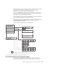
More information about the meaning of the bits in a BIND image, and some more
references, may be found in ACF/VTAM Version 3 Programming.
524 Customization Guide