Intel® Server Board SDS2 I/O Subsystem
Revision 1.2
Order Number: A85874-002
21
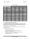
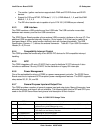
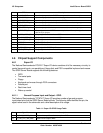
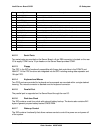
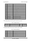
ISA Interrupt Description
INTR Processor interrupt
NMI NMI to processor
IRQ1 Keyboard interrupt
IRQ3 Serial port 1 or 2 interrupt from SIO device
IRQ4 Serial port 1 or 2 interrupt from SIO device
IRQ5
IRQ6 Floppy Controller
IRQ7
IRQ8_L Real Time Clock interrupt
IRQ9
IRQ10
IRQ11
IRQ12 PS/2 Mouse interrupt
IRQ14 Primary channel IDE interrupt
SMI* System Management Interrupt. General purpose indicator sourced by
the CSB5 and BMC to the processors
SCI* System Control Interrupt. Used by system to change sleep states and
other system level type functions
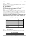
4.7.2 APIC Interrupt Routing
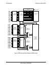
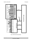
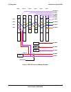
For APIC mode, the SDS2 interrupt architecture incorporates three Intel I/O APIC devices to
manage and broadcast interrupts to local APICs in each processor. The I/O APICs monitor each
interrupt on each PCI device including PCI slots in addition to the ISA compatibility interrupts IRQ
(0-15). When an interrupt occurs, a message corresponding to the interrupt is sent across a
three-wire serial interface to the local APICs. The APIC bus minimizes interrupt latency time for
compatibility interrupt sources. The I/O APICs can also supply greater than 16 interrupt levels to
the processor(s).
4.7.3 Serialized IRQ Support
The SDS2 Server Board supports a serialized interrupt delivery mechanism. Serialized IRQs
(SERIRQ) consists of a start frame, a minimum of 17 IRQ / data channels, and a stop frame.
Any slave device in the quiet mode may initiate the start frame. While in the continuous mode,
the start frame is initiated by the host controller.
4.7.4 IRQ Scan for PCIIRQ
The IRQ / data frame structure includes the ability to handle up to 32 sampling channels with the
standard implementation using the minimum 17 sampling channels. The SDS2 Server Board
has an external PCI interrupt serializer for PCIIRQ scan mechanism of CSB5 to support 16
PCIIRQs.


