


Intel® Server Board SDS2 Connections
Revision 1.2
Order Number: A85874-002
77
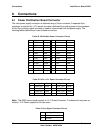
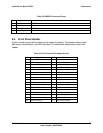
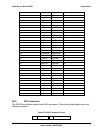
Table 59. HSBP-B Connector Pin-out
Pin Signal Name Description
1 IPMB_SDA 5 VSB Data Line
2 GND GND
3 IPMB_SCL 5 VSB Clock Line
4 I2C_ADR_CNTRL Address Control
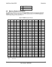
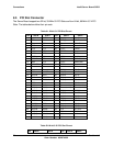
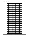
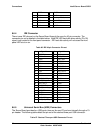
8.4 Front Panel Header
A 34-pin header is provided for cabling to the system front panel. The header contains reset,
NMI, power control buttons, and LED indicators. The table below details the pin-outs of the
header.
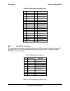
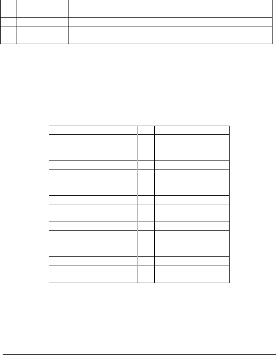
Table 60. Front Panel 34-Pin Header Pin-out
Pin Signal Name Pin Signal Name
1 Power LED Anode 2 5VSB
3 KEY 4 Fan Fail LED Anode
5 Power LED Cathode 6 Fan Fail LED Cathode
7 HDD Activity LED Anode 8 Power Fault LED Anode
9 HDD Activity LED Cathode 10 Power Fault LED Cathode
11 Power Switch 12 NIC#1 Activity LED Anode
13 GND (Power Switch) 14 NIC#1 Activity LED Cathode
15 Reset Switch 16 I2C SDA
17 GND (Reset Switch) 18 I2C SCL
19 ACPI Sleep Switch 20 Chassis Intrusion
21 GND (ACPI Sleep Switch) 22 NIC#2 Activity LED Anode
23 NMI to CPU Switch 24 NIC#2 Activity LED Cathode
25 KEY 26 KEY
27 ID LED Anode 28 System Ready Anode
29 ID LED Cathode 30 System Ready Cathode
31 ID Switch 32 HDD Fault Anode
33 GND (ID Switch) 34 HDD Fault Cathode