


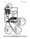

Intel® Server Board SDS2 Connections
Revision 1.2
Order Number: A85874-002
85
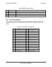
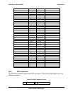
Pin Signal Name Description
1 DCD Data Carrier Detect
2 RXD Receive Data
3 TXD Transmit Data
4 DTR Data Terminal Ready
5 GND Ground
6 DSR Data Set Ready
7 RTS Request to Send
8 CTS Clear to Send
9 RI Ring Indicate
10 KEY Key
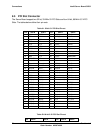
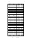
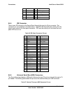
8.6.8 Parallel Port
One DB25 parallel port connector is provided on the rear I/O. The following table details the pin-
out of the connector.
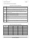
Table 72. DB25 Parallel Port Pin-out
Pin Signal Name Pin Signal Name
1 STROBE_L 14 AUTOFD_L
2 DATA0 15 ERROR_L
3 DATA1 16 INIT_L
4 DATA2 17 SLCT_INPUT_L
5 DATA3 18 GND
6 DATA4 19 GND
7 DATA5 20 GND
8 DATA6 21 GND
9 DATA7 22 GND
10 ACK_L 23 GND
11 BUSY 24 GND
12 PAPER_END 25 GND
13 SELECT
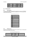
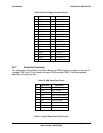
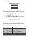
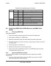
8.6.9 Keyboard and Mouse Connector
Two PS/2 ports are provided for keyboard and mouse and share a common housing. The top
one is labeled “mouse” and the bottom is labeled “keyboard,” although the board set supports
swapping these connections. The following table details the pin-out of the PS/2 connectors.
Table 73. Keyboard and Mouse PS/2 Connector Pin-out