


Server Management Intel® Server Board SDS2
Revision 1.2
Order Number: A85874-002
30
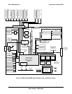
5.2 System Reset Control
Reset circuitry on the SDS2 Server Board looks at resets from the front panel, CSB5, ITP, and
processor subsystem to determine proper reset sequencing for all types of reset. The reset logic
is designed to accommodate a variety of ways to reset the system, which can be divided into the
following categories:
• Power-up reset
• Hard reset
• Soft (programmed) reset
The following subsections describe each category of reset.
5.2.1 Power-up Reset
When the system is disconnected from AC power, all logic on the Server Board is powered off.
When a valid input (AC) voltage level is provided to the power supply, 3.3 V standby power is
applied to the Server Board. A power monitor circuit on 3.3 V standby asserts
N_RST_BMCRST_L, causing the BMC to reset. The BMC is powered by 3.3 V standby and
monitors and controls key events in the system related to reset and power control.
After the system is turned on, the power supply asserts the N_PWRGD+00 signal after all
voltage levels in the system have reached valid levels. The BMC receives N_PWRGD+00 and
after approximately 500 ms it asserts N_RST_P6_PWRGOOD, which indicates to the
processors and CSB5 that the power is stable. Upon N_RST_P6_PWRGOOD assertion, the
CSB5 will toggle PCI reset.
5.2.2 Hard Reset
A hard reset can be initiated by resetting the system through the front panel switch. During the
reset, the Sahalee BMC de-asserts the N_RST_P6_PWRGOOD signal. After approximately 500
ms, it is reasserted, and the Power-up Reset sequence is done.
The Sahalee BMC is not reset by a hard reset. It may be reset at power-up.
5.2.3 Soft Reset
A soft reset causes the processors to begin execution in a known state without flushing the
caches or internal buffers. The keyboard controller located in the SIO or by the CSB5 can
generate soft resets. The output of the SIO (N_KBD_PINITL) is input to the CSB5.
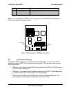
5.3 Intelligent Platform Management Buses
Management controllers and sensors communicate on the I
2
C-based Intelligent Platform
Management Bus. A bit protocol defined by the I
2
C Bus Specification, and a byte-level protocol
defined by the Intelligent Platform Management Bus Communications Protocol Specification,
provide an independent interconnect for all devices operating on this I
2
C bus. The IPMB extends
throughout the Server Board and system chassis. An added layer in the protocol supports
transactions between multiple servers on inter-chassis I
2
C bus segments.