


114 007-4857-002
6: Maintenance and Upgrade Procedures
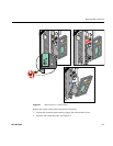
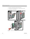
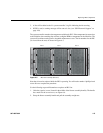
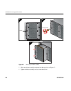
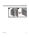
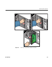
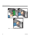
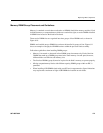
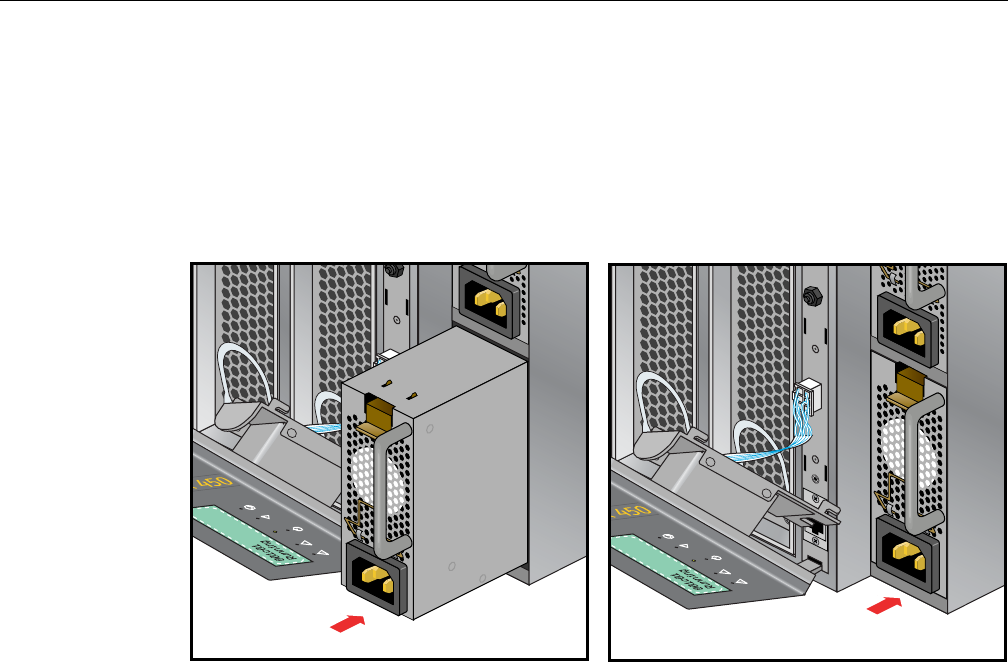
4. Install the new power supply with the retention latch at the top of the supply.
5. Slide the power supply into the chassis until the retention latch engages.
6. Reconnect the power cord to the power supply.
7. Reattach the L1 front panel using the information in “Remove and Replace the System
Control Display Panel” on page 110.
Figure 6-4 Replacing an IRU Power Supply
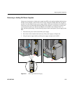
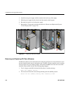
Removing and Replacing IRU Fans (Blowers)
The IRU fans (blowers) are located at the rear of the unit (see Figure 6-5). You will need to access
the rack from the back to remove and replace a fan. The IRU’s system controller issues a warning
message when a fan is not running properly. This means the RPM level of the fan is not within
tolerance. When an IRU fan fails, the following things happen:
1. The L1 display on the IRU with the failed fan shows a warning message
ATTN: Fan (number) warning
2. The console will show the same warning indicating the rack and IRU position
001c01 L2> Fan (number) warning limit reached @ 0 RPM