


NUMAlink Cabling the System IRUs
007-4857-002 29
NUMAlink Cabling the System IRUs
Some configurations of an Altix 450 system will consist of either two or more IRUs. This section
describes how to cable together these multiple units. If your system was shipped with all the cables
pre-installed, go on to the next section.
Note: If your system is made up of a single module, you can skip this section and proceed to
“Cabling the System IRUs to a Power Source” on page 31 for instructions to connect your system
to power.
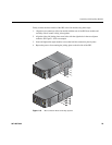
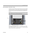
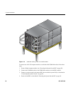
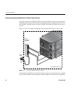
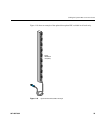
The primary IRU module (housing the system disk), connects to additional Altix 450 IRUs via the
module’s front NUMAlink connectors. Figure 1-14 shows an example.
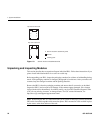
Note: Before you connect two Altix 450 IRUs to each other, you must assign unique system ID
numbers to the compute modules, as follows:
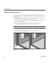
1. Designate one of the IRU modules as the master server and the other IRU chassis as the
slave.
2. Connect a console to the master IRU (see “Connecting the System Console” on page 36),
and then power on the IRU (see “Powering the System On and Off” on page 38).
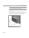
3. Use the <slotnumber> L1 command to set the secondary IRU’s ID number to a higher
number than the primary IRU’s ID number. For example, if the master IRU unit’s L1 prompt
indicates that its ID number is 01 (
001c01-L1>), then the subsidiary IRU ID number
should be 02 or higher (
001c02-L1>).
001c01-L1>brick slot 02
brick slot set to 02.
See the SGI L1 and L2 Controller Software User’s Guide (007-3938-00x) for more
information on L1 commands.