


44 007-4857-002
1: System Installation
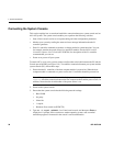
L1 Front Panel Controls
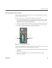
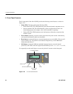
The L1 front panel of the Altix 450 IRU provides the following control features, as shown in
Figure 1-22:
• Status LEDs. The front panel has the following LEDs:
• Power button LED. This LED illuminates green when the internal components are on.
• Service-required LED. This LED illuminates yellow to indicate that an item is not
functioning properly (for example, a fan is off), but the IRU is operating.
• Failure LED. This LED illuminates red to indicate that a failure has occurred and the
module is down.
• Power button. Normally you power on the system from the system console. Alternatively,
you can press this button to power on the module.
• Reset button. Actuate this button to reset the internal processors and ASICs. The reset will
cause a memory loss. (To perform a reset without losing memory, see the NMI button
information that follows.)
• NMI button. Actuate the NMI (non-maskable interrupt) button to reset the internal
processor(s) and ASICs, and write register data and memory to the /var/adm/crash file.
Use a paperclip or other small object to access the “pin-hole” actuators on the front panel.
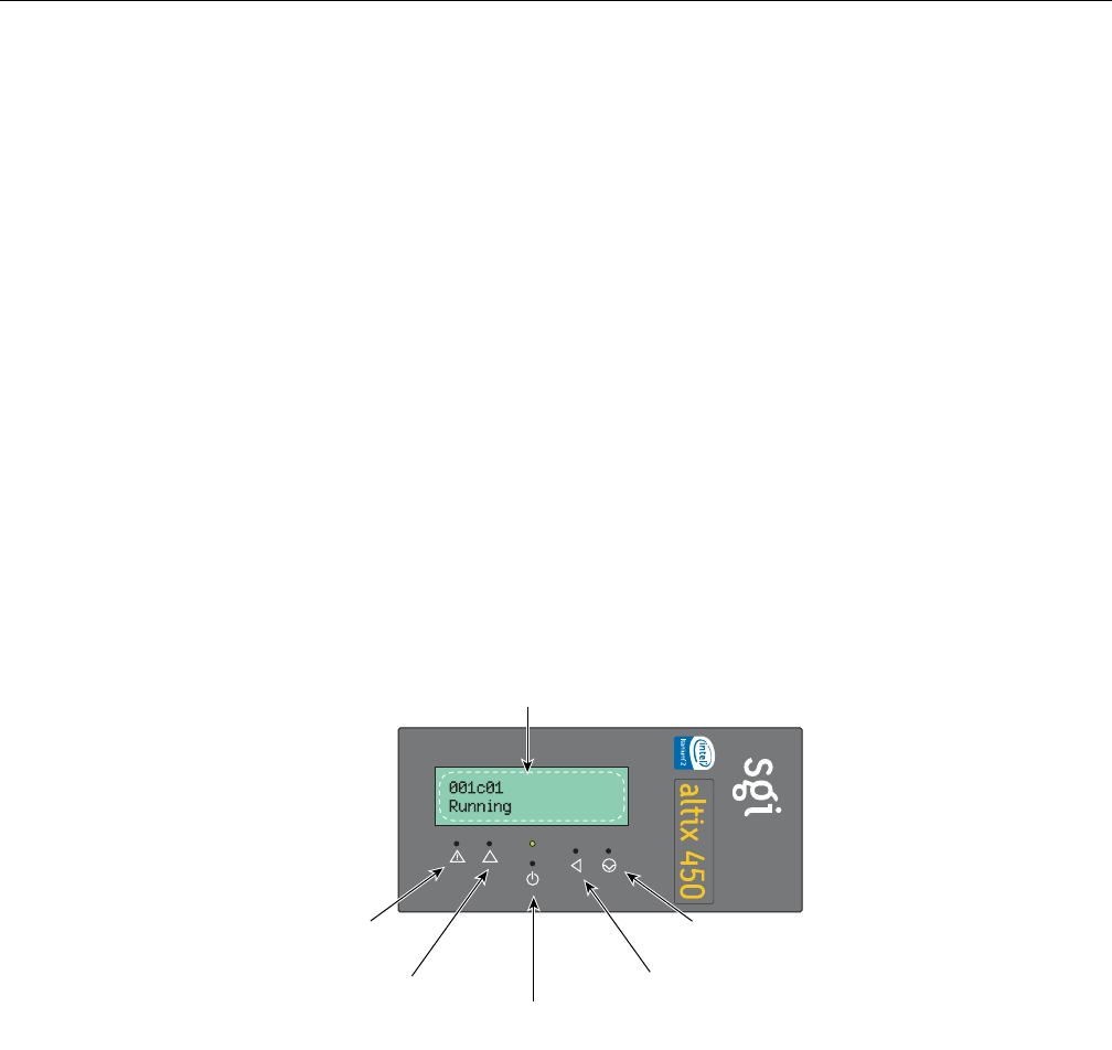
Figure 1-22 L1 Front Panel Functions
inside
TM
Service-required LED
F
ailure LED
Power button
with LED
Reset
L1 controller display
NMI