


Chapter 3: Connecting to the Line
iSPAN Serial WAN Adapter Users Guide 23
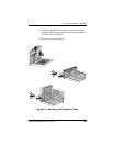
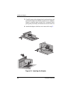
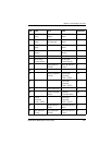
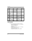
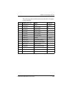
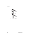
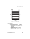
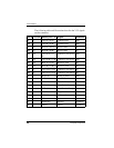
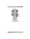
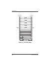
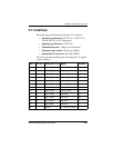
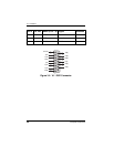
The following table and illustrations describe the V.24 signals
on the connector.
Pin # Name (CCITT #) Signal Direction
1 Shield(101) Shield Common
2 TxD(103) Transmit Data Out
3 RxD(104) Receive Data In
4 RTS(105) Ready to Send Out
5 CTS(106) Clear to Send In
6 DSR(107) Data Set Ready In
7 GND(102) Ground Common
8 DCD(109) Data Carrier Detect In
15 TXCin(114) Transmit Clock (DCE) In
17 RxC(115) Receive Clock In
20 DTR(108) Data Terminal Ready Out
22 RI(125) Ring Indication In
24 TxC(113) Transmit Clock (DTE) Out
25 -TEST Test In