


■ G.703, G.704, and G.706 E1 standards compliance
■ Independent internal and external clocking system
■ Loopback, bit error rate test (BERT), T1 facilities data link (FDL), and long buildout
diagnostics
For pinouts of cable connectors for T1 and E1 PIMs, see “E1 and T1 RJ-48 Cable
Pinouts” on page 237.
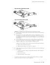
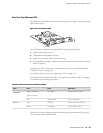
To install or remove a PIM, see “Replacing a PIM” on page 174.
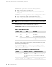
Status LEDs indicate port status. Table 26 on page 57 describes the meaning of the
LED states.
Table 26: Status LEDs for T1 and E1 Ports
DescriptionStateColor
Online with no alarms or failures.On steadilyGreen
Active with a local alarm. The router has
detected a failure.
On steadilyRed
Offline.OffUnlit
For alarms, see the configuring and monitoring alarms information in the J-series
Services Router Administration Guide.
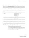
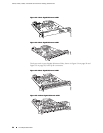
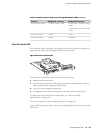
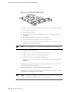
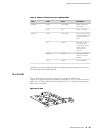
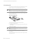
Dual-Port Channelized T1/E1/ISDN PRI PIM
The Dual-Port Channelized T1/E1/ISDN PRI PIM (Figure 31 on page 58) is a multiflex
interface card that allows you to configure a single interface as a channelized T1
interface or a channelized E1 interface. You can also configure ISDN PRI services on
a channelized T1 or E1 interface. The channelized T1/E1/ISDN PRI interface supports
up to 24 DS0 channels on a T1 interface and up to 31 DS0 channels on an E1
interface, in addition to supporting the features of regular (unchannelized) T1 and
E1 PIMs. Each interface can be configured as a single clear-channel, fractionalized,
or channelized interface.
NOTE: You cannot configure a channelized T1/E1/ISDN PRI interface through a J-Web
Quick Configuration page.
Field-Replaceable PIMs ■ 57
Chapter 3: PIM and VoIP Module Overview