


Replace Packet Fo
rwarding Engine Components
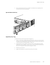
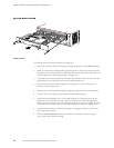
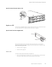
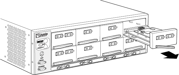
7. Unseat the PIC from the chassis:
• For a regular PIC, pull the right end of the PIC ejector lever away from the PIC
faceplate .
• For a quad-wide PIC, pull the end of each ejector lever away from the PIC faceplate,
toward the outer edges of the PIC.
8. GraspbothsidesofthePICfaceplateandslideitoutofthechassis.Donotusethe
ejector lever as a handle.
9. Place the PIC in the electrostatic bag or on the antistatic mat.
10. IfyouarenotreinstallingaPICintotheemptiedslotwithinashorttime,installablank
PIC panel ov
er the slot to maintain proper airflow in the chassis.
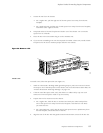
Figure 30: Remove a PIC
1310
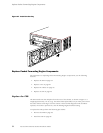
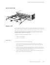
Install a PIC
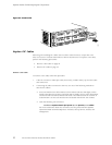
To instal
l a PIC, follow this procedure (see Figure 31):
1. Attach an electrostatic discharge (ESD) grounding strap to your bare wrist and connect
the stra
p to one of the ESD points on the chassis. For more information about ESD, see
“Prevent Electrostatic Discharge Damage” on page 134.
2. If the PIC uses fiber-optic cable, verify that there is a rubber safety cap over each
transceiver on the faceplate. Install a cap if necessary.
3. Prepare the PIC for insertion into the chassis:
• For a regular PIC, hold the PIC in one hand and w ith your other hand pull the
end of t
he ejector lever away from the P IC faceplate. Hold the lever out while
you insert the PIC.
• For a qu
ad-wide PIC, verify that the end of each ejector lever is pulled away from
the PIC faceplate, toward the ends of the PIC.
4. Align
the rear of the PIC with the guides located at the bottom corners of the PIC slot.
Replace Hardware Components
89