


RJ-48 Cable Pinou
ts for E1 and T1 PICs
to a laptop, modem, or other auxiliary unit, and the CONSOLE port connects it to a
management console. The ports are configured as data terminal equipment (DTE). For more
information,
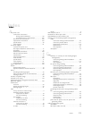
see “Routing Engine Interface Po rts and Status Indicators” o n page 15. Table
20 describes the DB-9 connector pinouts.
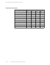
Table 20: DB-9 Connector Pinout
Pin Signal Direction Description
1DCD
<–
Carrier Detect
2
RxD
<–
Receive Data
3TxD
–>
Transmit Data
4
DTR
–>
Data Terminal Ready
5
Ground
—
Signal Ground
6DSR
<–
Data Set Ready
7RTS
–>
Request To Send
8CTS
<–
Clear To Send
9RING
<–
Ring Indicator
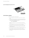
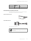
RJ-48 Cable Pinouts for E1 and T1 PICs
The E1 and T1 PICs use an RJ-48 cable, which is not supplied with the PIC.
To maintain agen cy approvals, use only a properly constructed, shielded
cable.
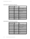
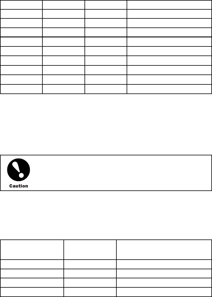
Table 21, Tab le 22, Table 23, and Table 24 describe the RJ-4 8 connector pinouts.
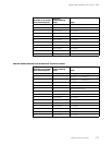
Table 21: RJ-48 Connector to RJ-48 Connector (Straight) Pinout
RJ-48 Pin (on T1/E1 PIC)
(Data numbering form)
RJ-48 Pin
(Data numb ering
form) Signal
11RX,Ring,–
22RX,Tip,+
44
TX, Ring, –
55TX,Tip,+
172 M5 and M10 Internet Routers Hardware Guide