


Connect PIC Cable
s
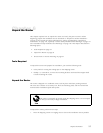
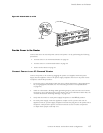
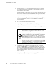
Figure 22: Routing Engine Ethernet Cable Connector
1063
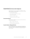
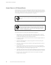
Connect to a Management Console or Auxiliary Device
To use a sys
tem console to configure and manage the Routing Engine, connect it to the
CONSOLE port on the craft interface. To use a laptop, modem, or other auxiliary device,
connect it to the appropriate AUX/MODEM port on the craft interface. Both ports accept an
RS-232 (EI
A-232) serial cable with DB-9/DB-9 connectors. One such cable is provided with
therouter.Ifyouwanttoconnectadevicetoboth ports, you must supply another cable. S ee
“Cable Specifications for Routing Engine Management Interfaces” on page 52. To connect a
manageme
nt console or auxiliary device, follow this procedure:
1. Turn off the power to the console or auxiliary device.
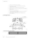
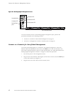
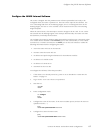
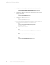
2. Plug the female end (shown in Figure 23) of the provided console cable into the
CONSOLE
or AUX/MODEM port (see Figure 21).
3. Usinga2
.5 mm flat-blade screwdriver, tighten t he screws on the connector.
4. Attach t
he other end of the cable to the console or auxiliary device.
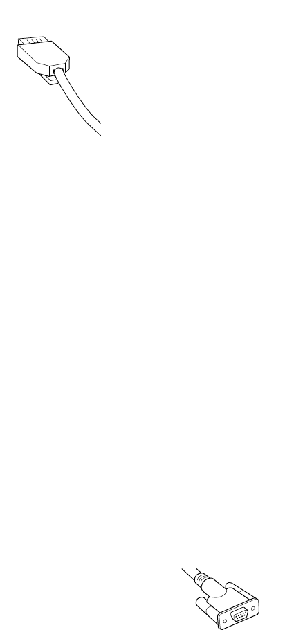
Figure 23: Console and Auxiliary Serial Port Connector
1027
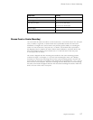
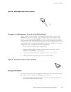
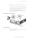
Connect PIC Cables
Now connect PICs to the network by plugging in network cable. To connect cable to the PICs,
follow this procedure (see Figure 24, which shows a fiber-optic PIC):
1. HavereadyalengthofthetypeofcableusedbythePIC.Forcablespecifications,see
the M5 and M10 Internet Routers PIC Guide.
Connect the Router and Perform Initial Configuration
63