


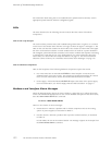
Replace Routing E
ngine Components
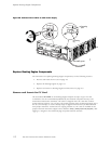
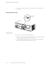
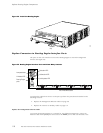
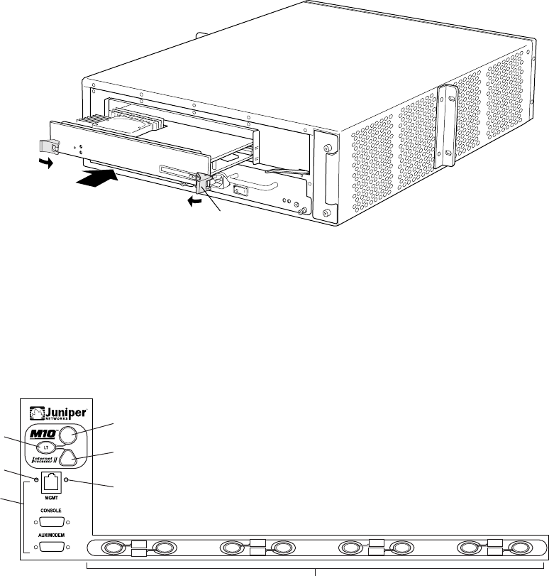
Figure 43: Install the Routing Engine
1313
Extractor
clip
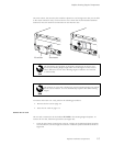
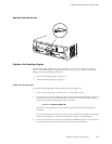
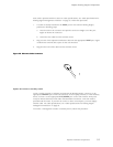
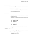
Replace Connectors to Routing Engine Interface Ports
The ports o
n the craft interface connect the Routing Engine to external management
devices(seeFigure44).
Figure 44: Routing Engine Interface Ports and Alarm Relay Contacts
R
1336
Red alarm LED
Lamp test button
Routing Engine
ports
PIC online/offline buttons
Yellow alarm LED
Link status LED
Activity status LED
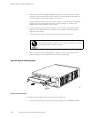
PIC0/3
PIC1/3
PIC0/2
PIC1/2
PIC0/1
PIC1/1
PIC0/0
PIC1/0
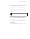
To replace the cables that connect to the ports, perform the procedures described in the
following sections:
• Replac
e the Management Ethernet Cable on page 118
• Replace the Console or Auxiliary Cable on page 11 9
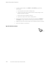
Replace the Management Ethernet Cable
To conn
ect the Routing Engine to a network for out-of-band management, connect an
Ethernet cable with RJ-45/RJ-45 connectors to the MGMT port on the craft interface. One
11 8 M5 and M10 Internet Routers Hardware Guide