


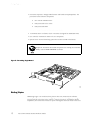
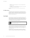

Power Supplies
• CONSOLE—Connects the Routing Engine to a system console through an RS-232
(EIA-232) serial cable.
• AUX/MODEM— Connects the Routing Engine to a l aptop, modem, or other auxiliary
device through an RS-232 (EIA-232) serial cable.
For information about the pinouts for the connectors, see “Cable Connector Pinouts”
on page 171.
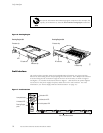
PIC Offline B
uttons
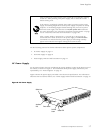
An offline button for each PIC is located below the PIC slot along t he bottom edge of the
craft interf
ace(seeFigure7).ThebuttonpreparesthePICforremovalfromtherouter
when pressed. The buttons are labeled with the PIC slot numbers. The PIC slots on an M5
router and in the upper FPC on an M10 router are numbered from 0/0 (zero/zero) through
0/3,rightto
left. The PIC slots in the lower FPC on an M10 router are numbered f rom
1/0 (one/zero) through 1/3,righttoleft.
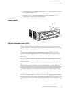
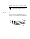
Power Supplies
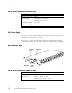
The router uses either AC or DC power. There are two load-sharing, isolated power s upplies
located at the bo ttom rear of the chassis, as shown in Figure 3. The power supplies
connect to
the midplane, which distributes power to router com ponents according to their
individual voltage requirements. When the power supplies are installed and operational, they
automatically share the electrical load. If a power supply stops functioning for any reason,
the remain
ing power supplies instantly begin providing all the power the router needs for
normal functioning and can provide full power indefinitely.
Mixing AC and DC power supplies is not supported. The t wo power supplies
must be either both AC or both DC.
An enable control signal on the output connector of each power supply ensures that the
supply i
s fully seated into the router midplane before the supply can be turned on. The
enable pin prevents a user-accessible energy hazard, so there is no interlocking mechanism.
The enable pin disables the voltage at the output connector if the power supply is not
turned
off before removal.
Power supplies are hot-removable and hot-insertable, as described in “Field-Replaceable
Units (
FRUs)” on page 3. To avoid electrical injury, carefully follow the instructions in
“Replace an AC Power Supply” on page 98 and “Replace a DC Power Supply” on page 104.
16 M5 and M10 Internet Routers Hardware Guide