


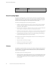
Craft Interface
For specific information about Routing Engine components (for example, the
capacity of th
eharddrive),issuetheshow chassis routing-engine command.
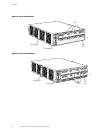
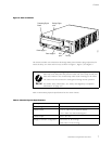
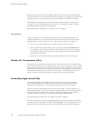
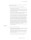
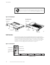
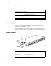
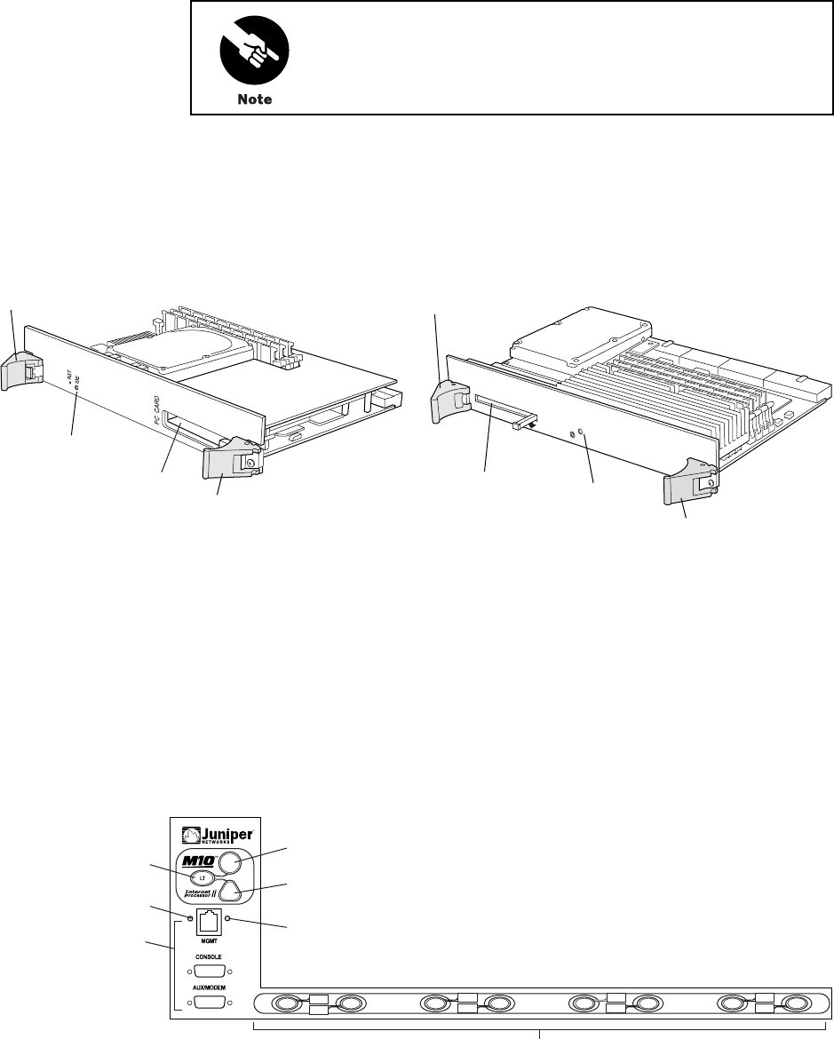
Figure 6: Routing Engine
JUNIPER NETWORKS LABEL THIS SIDE
1596
Extractor clip
PC card slot
RESET
HD
P
C
C
A
R
D
Extractor clip
PC card slot
LED
Extractor clipExtractor clip
LED
Routing Engine 333 Routing Engine 600
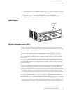
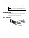
Craft Interface
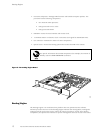
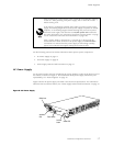
The craft interface provides status and troubleshooting information at a glance and has
buttons for deactivating alarms and preparing FPCs for removal. The L-shaped craft interface
is located along the left and bottom edges of thefrontofthechassis,asshowninFigure1
and Figure 2. It includes the elements shown in Figure 7. (The LEDs for the power supplies
are located on the power supply faceplate, rather than on the craft interface. For more
information, see “Power Supply LEDs and Self-test Button” on page 19.)
Figure 7: Craft Interface
R
1336
Red alarm LED
Lamp test button
Routing Engine
ports
PIC online/offline buttons
Yellow alarm LED
Link status LED
Activity status LED
PIC0/3
PIC1/3
PIC0/2
PIC1/2
PIC0/1
PIC1/1
PIC0/0
PIC1/0
14 M5 and M10 Internet Routers Hardware Guide