


Connect the Route
r to Management D evices
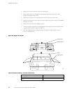
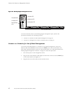
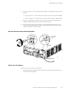
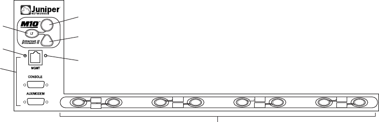
Figure 21: Routing Engine Management Ports
R
1336
Red alarm LED
Lamp test button
Routing Engine
ports
PIC online/offline buttons
Yellow alarm LED
Link status LED
Activity status LED
PIC0/3
PIC1/3
PIC0/2
PIC1/2
PIC0/1
PIC1/1
PIC0/0
PIC1/0
To connect external devices to the Routing Engine management ports, perform the
procedures described in the following sections:
• Connect to a Network for Out-of-Band Man agement on page 62
• Connect to a Management Console or Auxiliary Device on page 63
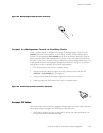
Connect to a Network for Out-of-Band Management
To connect
the Routing Engine to a network for out-of-band management, connect an
Ethernet cable with RJ-45/RJ-45 connectors to the MGMT port on the craft interface. One
such cable is provided with the router. For cable specifications, see “Cable Specifications for
Routing En
gine Management Interfaces” on page 52. Follow this procedure:
1. Turn off the power to the management device.
2. Plug one end of the Ethernet cable (Figure 22 shows the connector) into the MGMT port
on the cra
ftinterface(seeFigure21).
3. Plug the o
ther end of the cable into the network device.
62 M5 and M10 Internet Routers Hardware Guide