


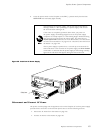
Replace Packet Fo
rwarding Engine Components
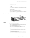
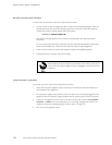
2. Verify that a rubber safety cap covers the S FP transceiver, installing one if n ecessary.
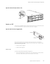
3. Orient the S FP over the port i n the PIC such that the connector end will enter the slot
first and the SFP connector faces the appropriate direction:
• If the PIC has t en SFP ports, the ports are arranged in two columns. The SFP
connector fa
ces to the right for ports in the left column, and to the left for ports
in the right column.
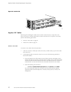
• If the PIC has
one or two SFP ports, the SFP connector faces to the left on platforms
in which FPCs install vertically in the chassis, and faces upward on platforms in
which FPCs install horizontally in the chassis.
4. Slide the SFP into the slot. If there is resistance, remove the SFP and try flipping it so
that the connector faces the other direction.
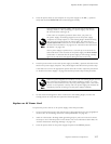
5. Remove the rubber safety cap from the transceiver and the end of the cable, and insert
the cable in
to the transceiver.
Do not look directly into the ends of fiber-optic cables or into the
transceivers on the interface faceplate. Single-mode fiber-optic cable
and the interfaces that use it (such as ATM and SONET/SDH interfaces)
emit laser light that can d amage your eyes.
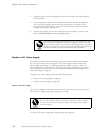
Do not leave a fiber-optic transceiver uncovered except when inserting
or removing cable. The safety cap keeps the port clean and prevents
accidental exposure to laser light.
Replace Hardware Components 97