


Replace Routing E
ngine Components
such cable is provided with the router. For cable specifications, see “Cable Specifications for
Routing Engine Management Interfaces” on page 52. Follow this procedure:
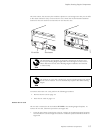
1. If a cable is already installed in the MGMT port for the relevant Routing Engine,
perform the following steps:
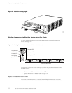
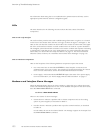
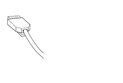
a. Press the tab on the connector and pull the connector straight out of the port.
Figure 45 sho
ws the connector.
b. Disconnec
t the cable from the network device.
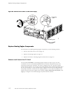
2. Plug one end
of the replacement Ethernet cable into the appropriate MGMT port. Figure
44 shows the external device ports on the craft interface.
3. Plug the other end of the cable into the network device.
Figure 45: Ethernet Cable Connector
1063
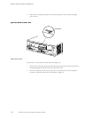
Replace
the Console or Auxiliary Cable
To use a system console to configure and manage the Routing Engine, connect it to the
appropr
iate CONSOLE port o n the craft interface. To use a laptop, modem, or other auxiliary
device, connect it to the appropriate AUX/MODEM port on the craft interface. Both ports
accept an RS-232 (EIA-232) serial cable with DB-9/DB-9 connectors. One such cable is
provid
ed with the router. If you want to connect a device to both ports, you must su pply
another cable. For cable specifications, see “Cable Specifica tions for Routing Engine
Management Interfaces” on page 52.
To connect a management console or auxiliary device, follow this procedure:
Replace Hardware Components
11 9