


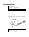

Routing Engine
The Routing Engine installs into a slot in the FEB at the rear of the chassis. The Routing
Engine is field-replaceable, but you must power down the router before removing it from
the chassis. P
acket forwarding halts until the Routing Engine is replaced and the router is
powered on. For replacement instructions, see “Replace the Routing Engine” on page 115.
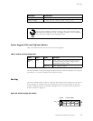
Routing Engine Components
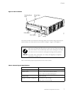
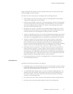
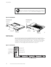
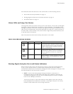
The Routing Engine (shown in Figure 6) is a two-board system with the following components:
• CPU—Runs JUN
OS Inter net software to maintain the router’s routing tables and routing
protocols. It has a Pentium-class processor.
• SDRAM—Provi
des storage for the routing and forwarding tables and for other Routing
Engine processes.
• Compact flas
h drive—Provides p rimary storage for software images, configuration files,
and microcode. The drive is fixed and inaccessible from outside the router.
• Hard drive—P
rovides secondary storage for log files, memory dumps, and rebooting
the system if the flash drive fails.
• PC card slot
—Accepts a removable PC card, which stores software images for system
upgrades.
• LED—Indica
tes disk activity for the internal IDE interface. It does not necessarily
indicate routing-related activity.
• Interfaces
for out-of-band management access—Provide information about
Routing Engine status to devices (console, laptop, or terminal server) that can be
attached to access ports located on the craft interface.
• EEPROM—Stores the serial number of the Routing E ngine.
• Reset butt
on—Reboots the Routing Engine w hen pressed.
• Extractor clips—Control the locking system that secures the Routing Engine in the
chassis.
The appear
ance and position of electronic c omponents or the PC card slot
on your Routing Engine might differ from Figure 6 and other figures in this
document
that depict the Routing Engine. These differences do not affect
Routing Engine installation and removal or functionality.
Hardware Component Overview 13