


– 92 –
APPENDIX D
PCI-1712/1712L User’s Manual
Advantech Co., Ltd.
www.advantech.com
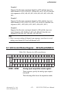
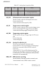
DA1_U/B D/A channel 1 unipolar or bipolar output
This bit specifies the output voltage of AO1 as unipolar or
bipolar.
0 means the output voltage is unipolar.
1 means the output voltage is bipolar.
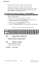
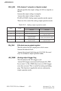
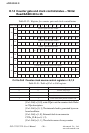
DAM1 to DAM0 Analog output operation mode register
These two bits control the analog output operation mode.
Table D-11: Analog output operation mode
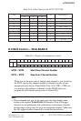
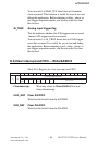
DA_CLK D/A clock source select register
This bit selects the D/A output pacer clock source.
0 means the internal clock.
1 means the external clock from pin AO_CLK. It is used
only in continuous output operation mode.
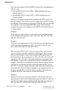
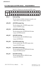
AO_TRGF Analog output trigger flag
This bit indicates the D/A trigger event.
1 means D/A trigger event occurred from pin AO_TRG.
If you write 1 to AO_TRGF, then it acts as if D/A trigger
event has occurred. This is useful for testing and debug
ging. This function is applicable only in continuously
output operation mode.
1MAD 0MAD
gninaeM
1HCA/D 0HCA/D
0 0 edoMnoitarepOeulaVelgniS edoMnoitarepOeulaVelgniS
0 1 edoMnoitarepOeulaVelgniS
tuptuOsuounitnoC
edoMnoitarepO
1 0
tuptuOsuounitnoC
edoMnoitarepO
edoMnoitarepOeulaVelgniS
1 1
tuptuOsuounitnoC
edoMnoitarepO
tuptuOsuounitnoC
edoMnoitarepO