


– 97 –
APPENDIX D
PCI-1712/1712L User’s Manual
Advantech Co., Ltd.
www.advantech.com
comes from its previous counter’s output in a round-robin
fashion. For example, the source of counter 0 comes from
the output of its previous counter, i.e. counter 2, whose
source in turn comes from counter 1, whose source comes
from counter 0,etc.
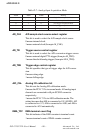
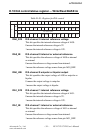
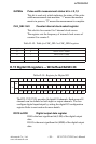
CPn Counter clock edge control register n = 0,1,2
This bit specifies whether the clock will act as a rising or
falling trigger.
0 means rising edge.
1 means falling edge.
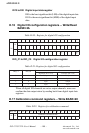
CQn Counter clock set register n = 0,1,2
When [Cn1: Cn0] = [0, 0], which means the clock input of
counter n is set by CQn through software, a pulse will be
generated when bit CQn being written to. For example, if a
“1” is written to CQn with an original value of “0”, then a
rising-edge pulse will be generated, which will serve as the
clock input of counter n. If a “0” is written to CQn with an
original value of “1”, then a falling-edge pulse will be
generated.
This function is necessary for users who want to load the
register data to the 82C54 chip.
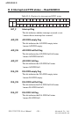
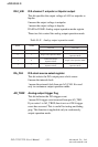
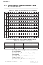
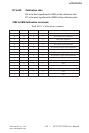
Gn1 to Gn0 Counter gate source control register n = 0,1,2
Table D-17: Table of Gn1 to Gn0 register
[Gn1: Gn0] = [0, 0], write GQn to set the counter gate. Refer
to CQn description.
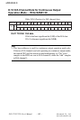
[Gn1: Gn0] = [0, 1], The gate source comes from the previ
ous counter’s output. The previous counter of counter 0 is
counter 2, of counter 1 is counter 0 and of counter 2 is
counter 1. The gate source of every counter comes from its
previous counter’s output in a round-robin fashion. For
example, the gate source of counter 0 comes from the
1nG 0nG gninaeM
0 0 nQGybtessietaG
0 1 tuptuos’retnuocsuoiverpmorfsemocetaG
1 0 etaglanretxemorfsemocetaG
1 1 tnemerusaemhtdiwesluprofesuetaG