


– 41 –
Chapter 5
PCI-1712/1712L User’s Manual
Advantech Co., Ltd.
www.advantech.com
channel.
In this mode, users need to set the clock source and trigger source
first, and then generate the output data to be stored in the memory
buffers of host PC. The host computer then transfers those data to be
written to the DACs from its buffers to the 32K-sample Output FIFO on
board. When it detects a trigger, the board outputs the values in the
Output FIFO to the DACs at the same time. When the samples in FIFO
decreases to less than half size (i.e. 16K samples) of the FIFO, then the
card will send a interrupt request to the host PC, which in turn sends
16K samples to the FIFO. This output operation will repeat until either
all the data is sent from the buffers or until you stop the operation.
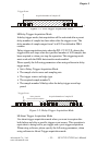
If the two D/A channels are both operating in continuous output
mode, the data in FIFO will be sent in an interlaced manner, i.e. The
“even” samples in the FIFO are sent to D/A channel 0, while the “odd”
samples to D/A channel 1.
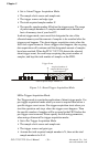
q Waveform Output Operation Mode
Waveform output operation mode is a particular and useful application
of continuous output operation mode. In this mode, users can output
the user-defined waveform pattern repetitively and continuously.
Before this operation can begin, users have to use software to allocate
the buffer memory and define the waveform pattern first. Then the host
computer will transfer the waveform pattern from its buffer allocated in
computer memory into the Output FIFO on the board, which in turn will
transfer the waveform pattern to the DACs. When the trigger event
occurs, each D/A channel running continuous output operation mode
will output waveform pattern from FIFO in specific clock rate.
D/A Output Clock Sources
The PCI-1712 can adopt both internal and external clock sources for
pacing the analog output of each channel:
w Internal D/A output clock with 16-bit Counter
w External D/A output clock that is connected to AO_CLK on the
PCLD-8712 screw terminal board
The internal and external D/A output clocks are described in more
detail as follows:
q Internal D/A Output Clock
The internal D/A output clock uses a 10 MHz time base. Conversions
start on the rising edge of the counter output. Through software to
specify the clock source as internal and the clock frequency to pace