


– 47 –
Chapter 5
PCI-1712/1712L User’s Manual
Advantech Co., Ltd.
www.advantech.com
appropriate depending on your application.
Please follow the procedure below when using software:
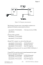
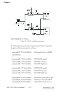
1 Select a counter (e.g. counter 0) to do rate generation.
2. Set the counter in mode 3 (Please refer to Intel
®
82C54 User’s
Manual).
3. Select the clock input of the counter. (Could be internal or
external)
4. Set the gate type of the counter to positive (logic-high).
5. Set the value of the counter to serve as the factor with which to
divide the clock input frequency.
6. Pull high the gate input and start rate generation.
For example, if the value of counter is 20 and the clock input frequency
is 1 MHz. Then the clock output frequency is 1 MHz / 20 = 50 KHz.
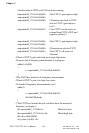
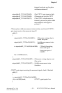
q One shot
Use one-shot mode to generate a single pulse signal from the counter,
which is triggered by the gate input signal.. You can use this pulse
output signal as an external digital (TTL) trigger source to start other
operations, such as analog input or analog output operations. When
the one-shot operation is triggered, only a single pulse is output. The
output pulse is always a negative pulse, whose width is determined by
the clock input signal and the value of the counter.
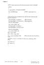
Please follow the procedure below when using software:
1. Select a counter to do one shot.
2. Set the counter in mode 1 (Please refer to Intel
®
82C54 User’s
Manual).
3. Select the clock source of the counter. (Could be internal or
external)
4. Set the gate type of the counter to positive (logic-high).
5. Set the value of the counter to serve as the factor with which to
multiply the clock input period.
6. Pull high the gate input and start to do one-shot output.
For example, if the value of counter is 20 and the frequency of clock
source is 1MHz, the period of the one-shot output source is 20 /
1 MHz = 20 ms.