


Figures
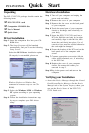
Figure 2-1: The Setup Screen of Advantech Automation Software .......8
Figure 2-2: Different options for Driver Setup .......................................9
Figure 2-3: The device name listed on the Device Manager ............... 11
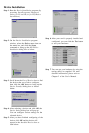
Figure 2-4: The Advantech Device Installation utility program ............12
Figure 2-5: The I/O Device Installation dialog box .............................. 12
Figure 2-6: The Device(s) Found dialog box .................................... 13
Figure 2-7: The Device Setting dialog box ......................................... 13
Figure 2-8: The Device Name appearing on the list of devices box .... 14
Figure 2-9: Analog Input tab on the Device Test dialog box ...............15
Figure 2-10: Analog Input tab on the Device Test dialog box ............... 16
Figure 2-11: Analog Output tab on the Device Test dialog box ............ 16
Figure 2-12: Digital Input tab on the Device Test dialog box ................ 17
Figure 2-13: Digital Output tab on the Device Test dialog box.............. 17
Figure 2-14: Digital output tab on the Device Test dialog box .............. 18
Figure 3-1: I/O connector pin assignments for the PCI-1712/1712L ... 20
Figure 3-2: Single-ended input channel connection ........................... 24
Figure 3-3: Differential input channel connection - ground reference
signal source ..................................................................25
Figure 3-4: Differential input channel connection - floating signal
source ............................................................................26
Figure 3-5: Analog output connections.............................................. 27
Figure 5-1: Post-Trigger Acquisition Mode ........................................ 35
Figure 5-2: Delay-Trigger Acquisition Mode .......................................35
Figure 5-3: About-Trigger Acquisition Mode ...................................... 36
Figure 5-4: Pre-Trigger Acquisition Mode .......................................... 37
Figure 5-5: PCI-1712/1712L Sample Clock Source ...........................38
Figure 5-6: Frequency measurement ................................................49
Figure 6-1: PCI-1712/1712L VR1 & TP5 ............................................ 55
Figure 6-2: Selecting the device you want to calibrate....................... 58
Figure 6-3: Warning message before start calibration .......................59