


– 48 –
Chapter 5
PCI-1712/1712L User’s Manual
Advantech Co., Ltd.
www.advantech.com
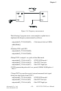
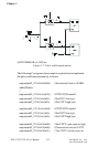
q Frequency measurement
The frequency measurement function helps user to measure the
frequency of the signal from counter-associated clock input on PCLD-
8712.
Frequency measurement needs two counters to implement. Use the
first counter to produce a one-shot pulse with defined pulse period to
be the second counter’s gate. Connect the signal source, whose
frequency is to be measured, to the clock input of the second counter.
Since the one-shot pulse generated from the first counter is always a
negative pulse, we have to set the gate input type of the second
counter as logic low for proper frequency measurement.
The second counter starts to count once the gate is set to low and
stops when the gate is high again after a period of time. Assume the
measured frequency signal is the regular pulse, then we can calculate
its frequency by the period of one-shot and the value of second
counter.
Please follow the procedure below when using software:
1. Select the first counter to do one shot and specify its pulse
period.
2. Connect the signal output CNT1_OUT of the first counter to the
second counter’s gate input CNT2_GATE.
3. Select the clock source of the first counter. (Could be internal or
external)
4. Set the gate type of the first counter to positive (logic-high), and
the second counter to negative (logic-low).
5. Reset the second counter to 65,535.
6. Pull high the gate input of the first counter and start to do
frequency measurement.
7. Read the value of the second counter.
8. Evaluate the frequency of the measured pulse.
For example, if frequency measurement is done with the second
counter value set at 65,535 and the period of one-shot from the first
counter set at 0.1 sec, then the value of the second counter we get
back is 43930. Thus, the frequency of measured pulse could be
calculated as (65535-43930)/0.1sec. = 216050 Hz.