


– 17 –
Chapter 2
PCI-1712/1712L User’s Manual
Advantech Co., Ltd.
www.advantech.com
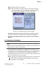
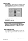
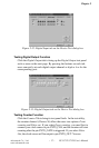
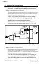
Figure 2-12: Digital Input tab on the Device Test dialog box
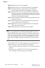
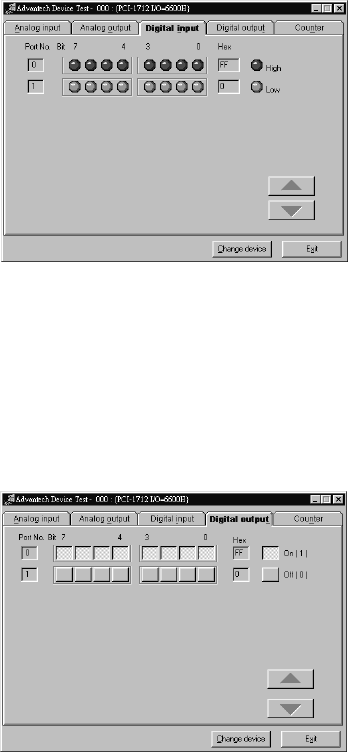
Testing Digital Output Function
Click the Digital Output tab to bring up the Digital Output test panel
such as seen on the next page. By pressing the buttons on each tab,
users can easily set each digital output channel as high or low for the
corresponding port.
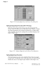
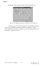
Figure 2-13: Digital Output tab on the Device Test dialog box
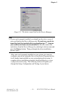
Testing Counter Function
Click the Counter Tab to bring its test panel forth. In the test utility,
the counter channel (Channel 0) offers the users two options: Event
counting and Pulse out. If you select Event counting, you need first to
connect your clock source to pin CNT0_CLK, and the counter will start
counting after the pin CNT0_GATE is triggered. If you select Pulse
Out, the clock source will be output to pin CNT0_OUT. You can