


– 87 –
APPENDIX D
PCI-1712/1712L User’s Manual
Advantech Co., Ltd.
www.advantech.com
Example 4
Suppose that the start scan input channel is AI14 and the stop scan
input channel is AI3. If AI14 is D, AI0 and AI1 are S, AI2 is D, then the
scan sequence is AI14, AI0, AI1, AI2, AI14, AI0, AI1, AI2, AI14, AI0,
AI1...
Example 5
Suppose that the start scan input channel is AI11 and the stop scan
input channel is AI15. If AI11 is S, AI12 is D, AI14 is D, then the scan
sequence is AI11, AI12, AI14, AI11, AI12, AI14, AI11, AI12...
Example 6
Suppose that the start scan input channel is AI4 and the stop scan
input channel is AI7. If AI4 is S, AI5 is D, AI6 is D, then the scan
sequence is AI4, AI5, AI7, AI4, AI5, AI7, AI4, AI5...
Note
✎ This is an error setting of channel scan sequence, user have to avoid
setting even channel as S and odd channel as D.
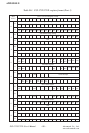
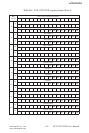
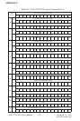
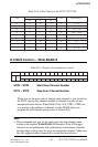
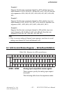
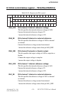
D.7 A/D Control/Status Register — Write/Read BASE+6
Table D-6: Register for A/D control/status
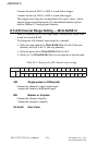
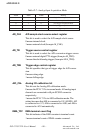
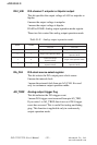
ADM2 ~ ADM0 Analog input acquisition mode register
These registers specify the analog input acquisi
tion mode.
The following table shows the acquisition mode.
.ddAesaB 51 41 31 21 11 01 9 8 7 6 5 4 3 2 1 0
6
W
retsigerlortnocD/A
T_IA
FGR
MD
T_A
FC
_OIA
LAC
_DA
ERT
_DA
RT
_DA
KLC
2MDA 1MDA 0MDA
R
retsigersutatsD/A
T_IA
FGR
AMD
FCT_
_DA
ERT
_DA
RT
_DA
KLC
2MDA 1MDA 0MDA