


– 33 –
Chapter 4
PCI-1712/1712L User’s Manual
Advantech Co., Ltd.
www.advantech.com
Chapter
5
5. Principles of Operation
This chapter describes the analog input, analog output, digital I/O and
counter/timer features of the PCI-1712/1712L card.
5.1 Analog Input Features
This section describes the following features of the analog input (A/D)
of PCI-1712/1712L card:
w Analog input ranges and gains
w Analog input acquisition modes
w A/D sample clock sources
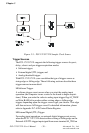
w Trigger sources
w Analog Input Data Format
Analog Input Ranges and Gains
Each channel on the PCI-1712/1712L can measure unipolar and bipolar
analog input signals. A unipolar signal can range between 0 to 10 V
FSR, while a bipolar signal extends within ± 10 V FSR.
The PCI-1712/1712L is able to set different input ranges for each
channel. When the channels are set as unipolar or bipolar input in FSR,
the sampling rate can be up to 600 kS/s, but when there is a mixed
combination of unipolar and bipolar inputs, it can operate only with a
rate up to 400 kS/s.
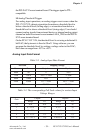
The PCI-1712/1712L also provides various gain levels that are program-
mable per channel. Table 5-1 lists the effective ranges supported by the
PCI-1712/1712L using these gains.
Table 5-1: Gains and Analog Input Range
For each channel, choose the gain level that provides most optimal
range that can accommodate the signal range you have to measure. For
detailed information, please refer to Appendix D.5 A/D Channel Range
Setting.
niaG egnaRtupnIgolanAralopinU egnaRtupnIgolanAralopiB
5.0 A/N V01±
1 V01~0 V5±
2 V5~0 V5.2±
4 V5.2~0 V52.1±
8 V52.1~0 V526.0±