


– 99 –
APPENDIX D
PCI-1712/1712L User’s Manual
Advantech Co., Ltd.
www.advantech.com
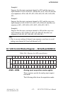
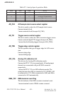
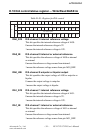
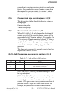
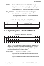
GATESn Pulse width measurement status bit n = 0,1,2
This bit is read only which indicates the status of the pulse
width measurement state machine. “1” means the measure
ment is in process; “0” means the measurement is complete.
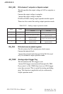
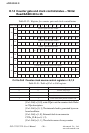
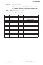
CLK_SEL1 & 0 Counter internal clock select register
This clock is for counter 0 to 2 internal clock source.
The register sets the frequency of internal clock source of
counter 0 to counter 2.
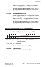
Table D-18: Table for CLK_SEL1 to CLK_SEL0 register
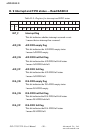
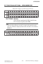
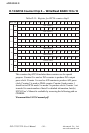
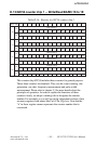
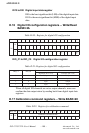
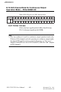
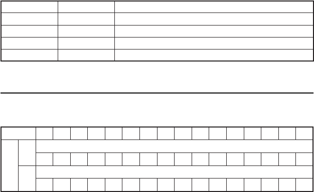
D.15 Digital I/O registers Write/Read BASE+28
Table D-19: Register for Digital I/O
The PCI-1712/1712L provides 16 digital I/O channels. Each group of 8
channels can be defined as both input or output channels. You can
configure digital input/output by setting the digital I/O configuration
register. Refer to next section for more details.
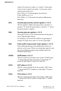
DO15 to DO0 Digital output data register
DO0 is the least significant bit (LSB) of the digital output
data.
DO15 is the most significant bit (MSB) of the digital output
data.
1LES_KLC 0LES_KLC gninaeM
0 0 zHM01sikcolclanretnI
0 1 zHM1sikcolclanretnI
1 0 zHK001sikcolclanretnI
1 1 zHK01sikcolclanretnI
.ddAesaB 51 41 31 21 11 01 9 8 7 6 5 4 3 2 1 0
82
W
tuptuOlatigiD
51OD 41OD 31OD 21OD 11OD 01OD 9OD 8OD 7OD 6OD 5OD 4OD 3OD 2OD 1OD 0OD
R
tupnIlatigiD
51OD 41OD 31OD 21OD 11OD 01OD 9OD 8OD 7OD 6OD 5OD 4OD 3OD 2OD 1OD 0OD