


– 51 –
Chapter 5
PCI-1712/1712L User’s Manual
Advantech Co., Ltd.
www.advantech.com
printf(“Counter 2 = %u \n”,old_count);
old_count = 0;
}
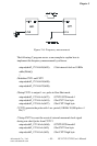
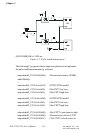
q Pulse width measurement
The pulse width measurement function helps user measure the period
of the signal from counter-associated clock input on PCLD-8712.
Pulse width measurement also needs two counters to implement. Use
the first counter to measure the positive period of the pulse and
second counter to measure the negative period of the pulse (In DLL
driver, it uses CNT1 and CNT2 to implement the pulse width measure-
ment function). To implement the function, we have to connect the
measured pulse signal to the gate of the two counters, and the same
clock source to the clock of the two counters.
Please follow the procedure below when using software:
1. Select the two counters to do event counting.
2. Set both counters in mode 0 (Please refer to Intel
®
82C54 User’s
Manual).
3. Connect the measured pulse signal source to pin CNT1_GATE
and CNT2_GATE of both counters
4. Select the clock source of the counter. (Could be internal
external)
5. Connect the clock source to pin CNT1_CLK and CNT2_CLK of
both counters.
6. Set the gate type of the first counter to negative (logic-low).
7. Set the gate type of the second counter to positive (logic-high).
8. Reset both counters to 65,535 and the counters now are ready
for pulse width measurement.
9. On the first incoming pulse, each counter will start measuring
specifically the positive and negative period of the first pulse
cycle.
10.Read the value of both counters.
11.Calculate the width of measured pulse.
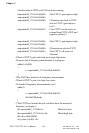
For example, if the clock source is of 1KHz, and the reset value of both
counters set to 65,535, then we get a value of 40000 for the first
counter, and 50000 for the second counter. Thus the negative pulse
period is (65535-40000)/1K=25.535 sec, and the positive pulse period is