


– 98 –
APPENDIX D
PCI-1712/1712L User’s Manual
Advantech Co., Ltd.
www.advantech.com
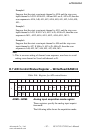
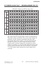
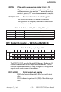
output of its previous counter, i.e. counter 2, whose gate
source in turn comes from counter 1, whose gate source
comes from counter 0, etc.
[Gn1: Gn0] = [1, 0], External gate is on connector
CNTn_GATE (n = 0, 1, 2).
[Gn1: Gn0] = [1, 1], this mode is for pulse width measure
ment only.
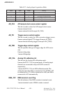
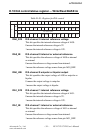
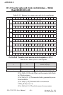
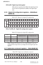
GPn Counter gate polarity control register n = 0,1,2
This bit specifies whether the gate polarity is positive or
negative. “0” means the gate polarity is positive; “1” means
the gate polarity is negative.
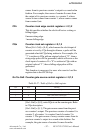
GQn Counter gate set register n = 0,1,2
When [Gn1: Gn0] = [0, 0], which means the counter gate is
set by GQn through software.
For example, you can write 0 to GQN to set gate input of
counter n as logic low or write 1 to set it as logic high.
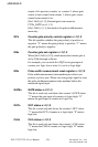
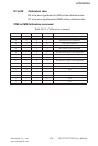
GRn Pulse width measurement reset register n = 0,1,2
Pulse width measurement state machine just allows one
positive cycle to pass. Please use rising-edge signal to reset
the pulse width measurement state machine before the
measured signal input.
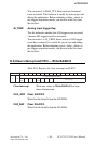
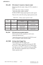
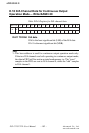
GATEn GATE status n = 0,1,2
This bit is read-only and shows the counter’s GATE status.
“1” means the gate input of counter n is logic-high; “0”
means the gate input of counter n is logic low.
OUTn OUT status n = 0,1,2
This bit is read-onlyand shows the counter’s OUT status.
“1” means the OUT of counter n is logic-high; “0” means
logic low.
CLKn CLK status n = 0,1,2
This bit is read-only and shows the counter’s CLK status.
“1” means the CLK of counter n is logic-high; “0” means
logic low.