


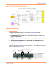

2: Introduction
xSenso User Guide 19
a. DeviceInstaller installation directory (typically at c:\Program File\Lantronix\Device
Installer\4.3).
b. Follow the instructions inAppendix E: USB-CDC-ACM Device Driver File for Windows
Hosts to create the .inf file and follow the windows driver installation steps as outlined
above.
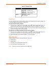
2. Connect the USB cable to the MGMT (USB) port of the xSenso device.
3. Connect the USB cable from the xSenso to the USB port on your computer.
4. Apply power. If drivers are installed, a virtual com port will be created on the computer.
5. Launch an emulation program terminal (e.g., Tera Term) and select the virtual com port.
6. Open up the virtual com port. The serial setting should be 9600, 8, none, and 1.
7. Click OK.
8. Press Enter in the terminal window. You will be prompted to login.
9. Login to the xSenso to configure it. The default login and password:
- User Name: admin
- Password: PASS
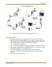
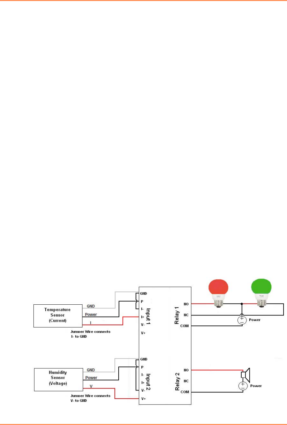
xSenso Wiring Example
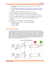
In Figure 2-3 below, there are two sensors connected to the inputs of the xSenso. One is the
temperature sensor and the other is the humidity sensor. In this example, Relay 1 is associated
with the temperature sensor and Relay 2 with the humidity sensor. In Relay 1, the Normally Open
(NO) pin allows the green light to stay on under normal operations. Once the Normally Closed
(NC) pin is activated, the green light will be turned off and the red light will be turned on indicating
an alarm condition. The threshhold ranges can be defined within the xSenso web interface. In
Relay 2, a buzzer is connected to Normally Open (NO) pin and once the alarm condition is met,
the relay will be closed and the buzzer will sound.
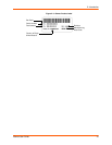
Figure 2-3 xSenso Wiring Diagram