


5: Installation of xSenso 21R2
xSenso User Guide 35
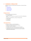
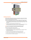
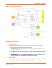
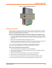
xSenso 21R2 Block Diagram
Figure 5-1 xSenso 21R2 Isolation Block Diagram
Hardware Components
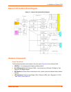
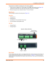
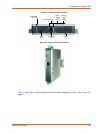
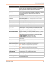
Front/Top Panel
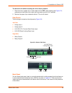
The following components are located on the front panel (Figure 5-2) of the xSenso 21R2:
USB Port - for managing and configuring xSenso device.
RJ-45 Ethernet Port (with Ethernet LEDs) - can connect to an Ethernet (10 Mbps) or Fast
Ethernet (100 Mbps) network.
RST Button (the Reset Button inside the pin hole) - power cycles and restores factory default
settings.
LED Indicators (4 Analog Input/Output LEDs, 2 Ethernet LEDs, and 1 Diagnostic “X” LED)
- see Table 5-4 and Table 5-5 to learn how to read the LED indicators.
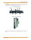
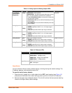
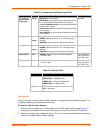
LED Indicators
The Analog Input LEDs, the Relay Output LEDs, the Ethernet LEDs, and the Diagnostic “X” LED
are all located on the front panel of the xSenso device (Figure 5-2).