


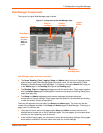
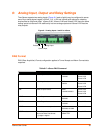
9: Analog Input, Output and Relay Settings
xSenso User Guide 55
Analog Input
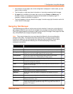
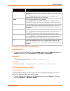
Table 9-4 Analog Input Settings
Input Settings Description
Display Select to enable or disable a scaled input value to be displayed with designated title
and units in the web manager, XML and CLI analog chanel as well as Tunnel and
Action Connect application. You can hide an input by disabling it if you are not using it.
Title Enter the analog input title as it will appear in web manager, XML and CLI. Leave this
field blank to utilize the default “Input N”, where N is the analog input number. For
example, you can name the reading, “Temperature”, if a temperature sensor is
connected to the xSenso device.
Range Select input range from drop-down menu. Select the measurement range closest to
your sensor output to get the most accurate measurement.
Select 20mA when input is connected to the I+ and I- terminals.
Select 100nV, 1V or 10V when input is connected to the V+ and V- terminals.
Adjustment Select the offset adjustment:
Select Simple offset so that the offset value is simply added to each analog input
with the result presented as an analog reading.
Select Scale and offset to linearly map each analog input sample to its reading value
via specification of two points (one near each end of the linear mapping range).
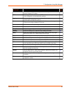
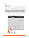
Input Low Enter the Input Low value which will be presented as the Reading Low value. For
example, if a sensor measures -40
° to 100°C with an output of 0 to10V, you can input
input low 0
°, input high 10°, reading low -40°, reading high 100° and unit "C".
Reading Low Enter the Reading Low value which will be converted from the Input Low value.
Input High Enter the Input High value which will be presented as the Reading High value.
Reading HIgh Enter the Reading HIgh value which will be presented as the Input HIgh value.
Offset Enter the offset value through which each sampled analog input value may be
adjusted. Offset may be positive or negative.
Decimal Point Specify the maximum number of digits to be displayed to the right of the decimal point,
according to the accuracy of signal source. Reading is always limited to have at 5
significant figures at most. For example, if the connected analog output sensor has an
accuracy of 0.1
°C, you can select decimal point to be 1.
Units Enter the unit as it will appear after the presented analog input value. For example, you
can input C or F if a temperature sensor is connected.
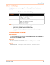
Alarm Type Select alarm type to enable monitoring for high and/or low analog input readings:
Select either High or High and Low to enable monitoring for a reading at or above
the specified Alarm High value.
Select Low or High and Low to enable monitoring for a reading at or below the
specified Alarm Low value.
Select None to disable monitoring reading for alarm low and/or high values.
Alarm High Specify the Alarm High value; an analog input reading above this value that persists
for Delay seconds will turn on the alarm.
Alarm Low Specify the Alarm Low value; an analog input reading below this value that persists for
Delay seconds will turn on the alarm.
Delay Specify the Delay value in seconds; an analog input high or low reading that persists
for Delay seconds will turn on the alarm.