


3: Installation of xSenso
xSenso User Guide 24
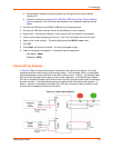
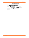
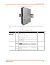
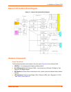
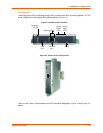
Figure 3-3 xSenso Top/Front View
Table 3-4 and Table 3-5 below explain the LED information displayed in Figure 3-2 and Figure 3-3
above.
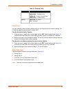
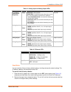
Table 3-4 Analog Input LEDs
LED Color ON OFF
“X” on top of
xSenso device
(Diagnostic)
Orange ORANGE ON - power present
ORANGE Blink - during boot process after power cycle or
reset. Also blink patterns represent error conditions:
Loss of Redundant Power: one slow blink followed by
two fast blinks (repeat)
No Ethernet Link: two slow blinks followed by two fast
blinks (repeat)
No IP Address: three slow blinks followed by three fast
blinks (repeat)
No power
Analog Input 1 Green
or
Orange
Input Type (voltage or current)
GREEN represents 100mV, 1V or 10V input range is
selected
ORANGE represents 20mA input range is selected
Input not utilized
Analog Input 2 Green
or
Orange
Input Type (voltage or current)
GREEN represents 100mV, 1V or 10V input range is
selected
ORANGE represents 20mA input range is selected
Input not utilized